
Turn an entire wall
becomes one display
— rather than simply placing several screens together
Distributed LED wireless-display architecture: sources connect to nearby nodes, return over an IP network and are managed by a unified control platformWindows · roaming · overlays · scenariosYuqi provides solution design, equipment selection and supply coordination, on-site installation and commissioning, and operations handover.
One wall, multiple sources, arranged your way
On the same video wall, laptops, video conferences, surveillance and cameras can be freely arranged, moved and overlaid. The demonstration below switches between common layouts every 3.4 seconds.
Why centralized matrices often complicate retrofit projects
Projects are often held back less by the display itself than by signal routing, fault ownership and future expansion. A distributed architecture addresses these concerns within one design.
All signals must be cabled back to the equipment room
- 01Each source needs a dedicated cable run to the equipment room. Retrofitting finished spaces may require wall or floor work and extended fire-safety or property approvals.
- 02HDMI and DVI signals begin to degrade beyond 15 metres. Longer runs require a fibre matrix, with costs rising as the number of channels increases.
- 03Adding one signal means another card and downtime for installation, making each expansion a risk.
- 04A matrix or video-wall processor can be a single point of failure: a fault may blank the entire wall and require on-site intervention.
- 05Cascaded devices lack a shared clock, causing tearing and timing differences across screens, especially in fast-moving scenes.
- 06Displays, matrices and installation are handled by different suppliers, leaving responsibility unclear when faults occur.
Connect signals locally and carry them over a unified network
- 01Connect sources to nearby encoding nodes and reuse existing network cabling or wireless backhaul where suitable. Installation is assessed against site conditions; reversible methods can be prioritized in existing venues.
- 02Use standard IP transport as the primary approach. Where cabling is not feasible, assess wireless endpoints against distance, obstructions and interference.
- 03Add nodes and licenses as the project grows, with expansion boundaries defined in the design and acceptance appendices.
- 04Nodes operate independently with dual-server hot standby, dual links and dual power. A single-point failure affects that channel rather than the entire wall.
- 05A unified network clock provides frame-level synchronization with less than one frame of cross-screen variance, avoiding tearing and misalignment at joins.
- 06One control platform covers the full signal path, with remote diagnosis, visible system status and fault location down to the node ID.
Five space types, each with different design constraints
Viewing distance, ambient light, operating hours and content determine display selection and system design. We do not apply one configuration to every room.

Meetings should not be interrupted by cabling or technical steps
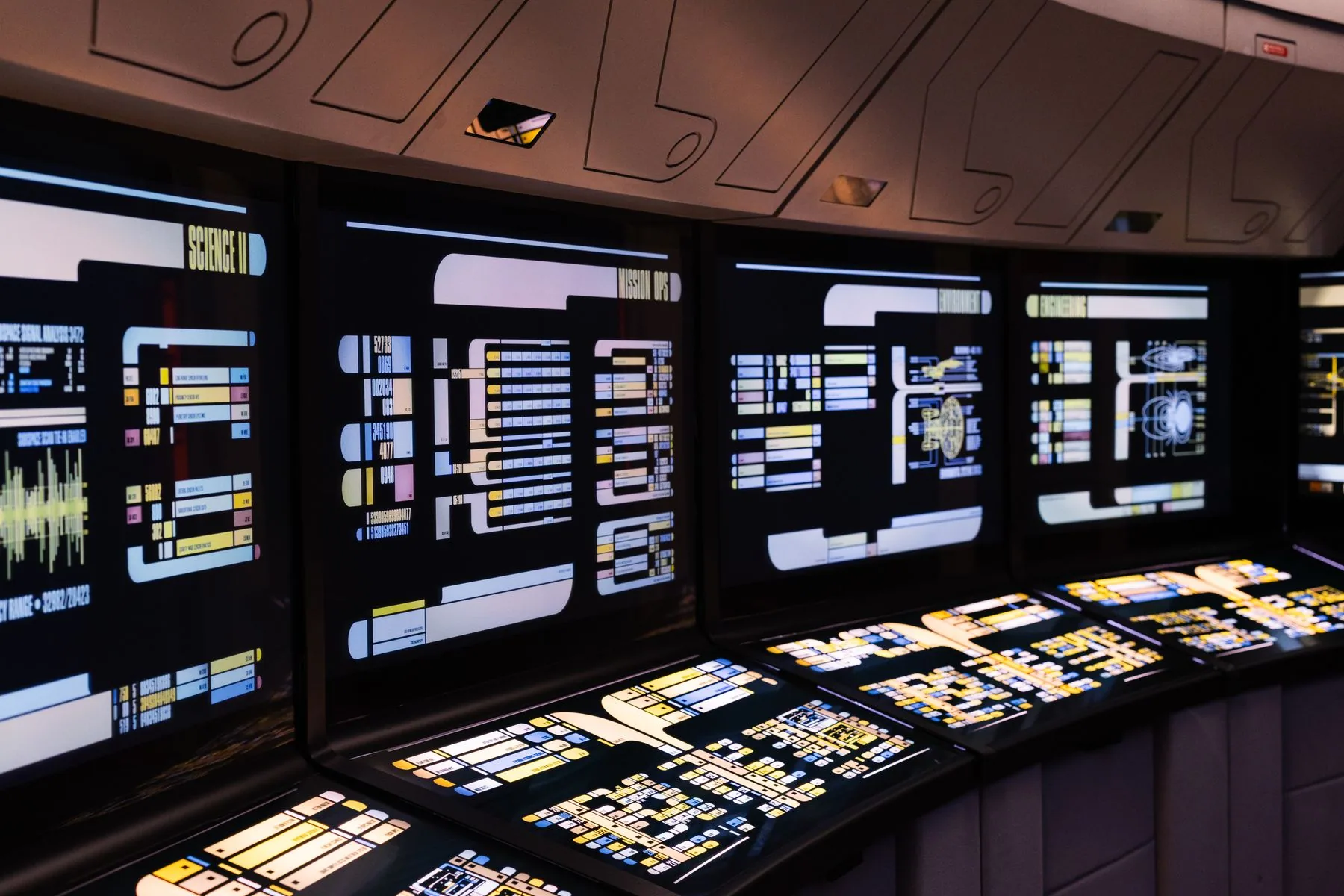
Wireless sources can join the video wall alongside laptops, conference systems, document cameras and surveillance feeds. Call up a layout before a meeting, adjust it during the session and return to standby afterward. Display pitch and brightness are selected for viewing distance and site conditions.
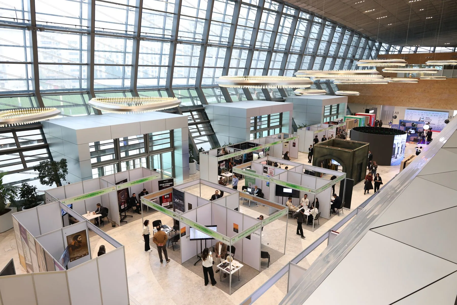
Curved, custom and immersive displays shaped around the space
Supports curved, cylindrical, wave, floor-tile and transparent display forms with unit-level geometry correction. Media-server and sensor-integration interfaces can be planned for content systems.
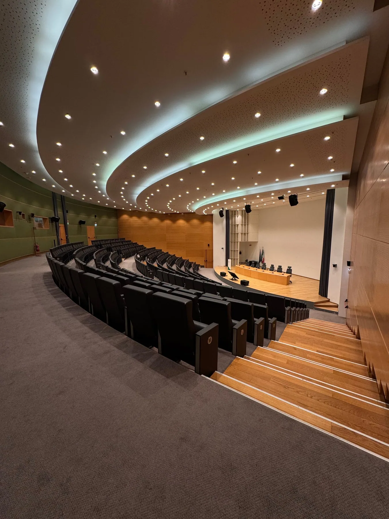
Main screen, secondary screens and captions under one system
The main screen carries presentations and live streams; side screens provide confidence display and prompts, while a dedicated lower zone displays captions. The system can connect to a production console, recording equipment and streaming output.
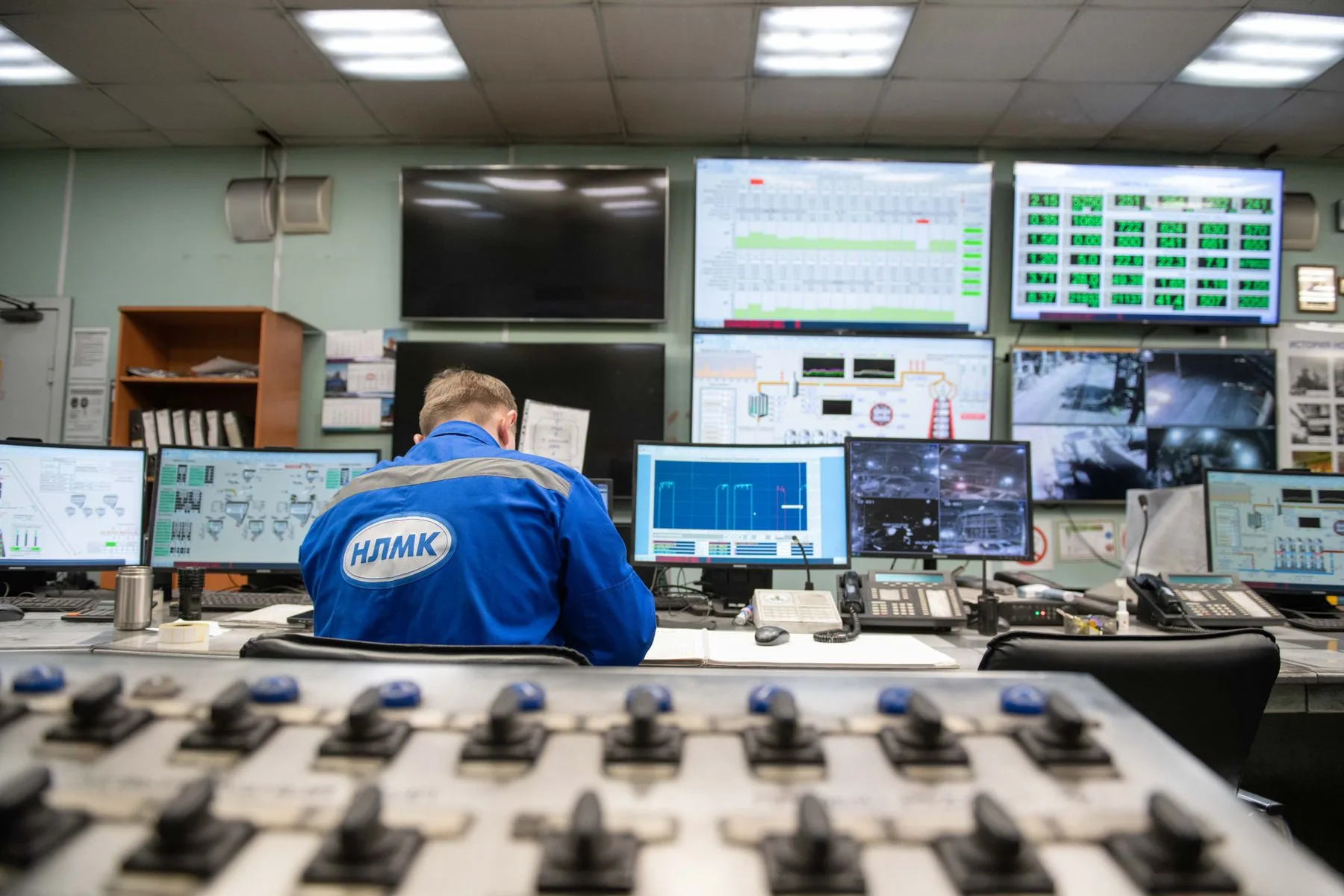
For spaces where critical operations cannot tolerate a blank screen
Dual-server hot standby, redundant links and power supplies, KVM operator coordination and one-click scenario switching. Node status is visible on the control wall, with automatic failover and alerts for anomalies.
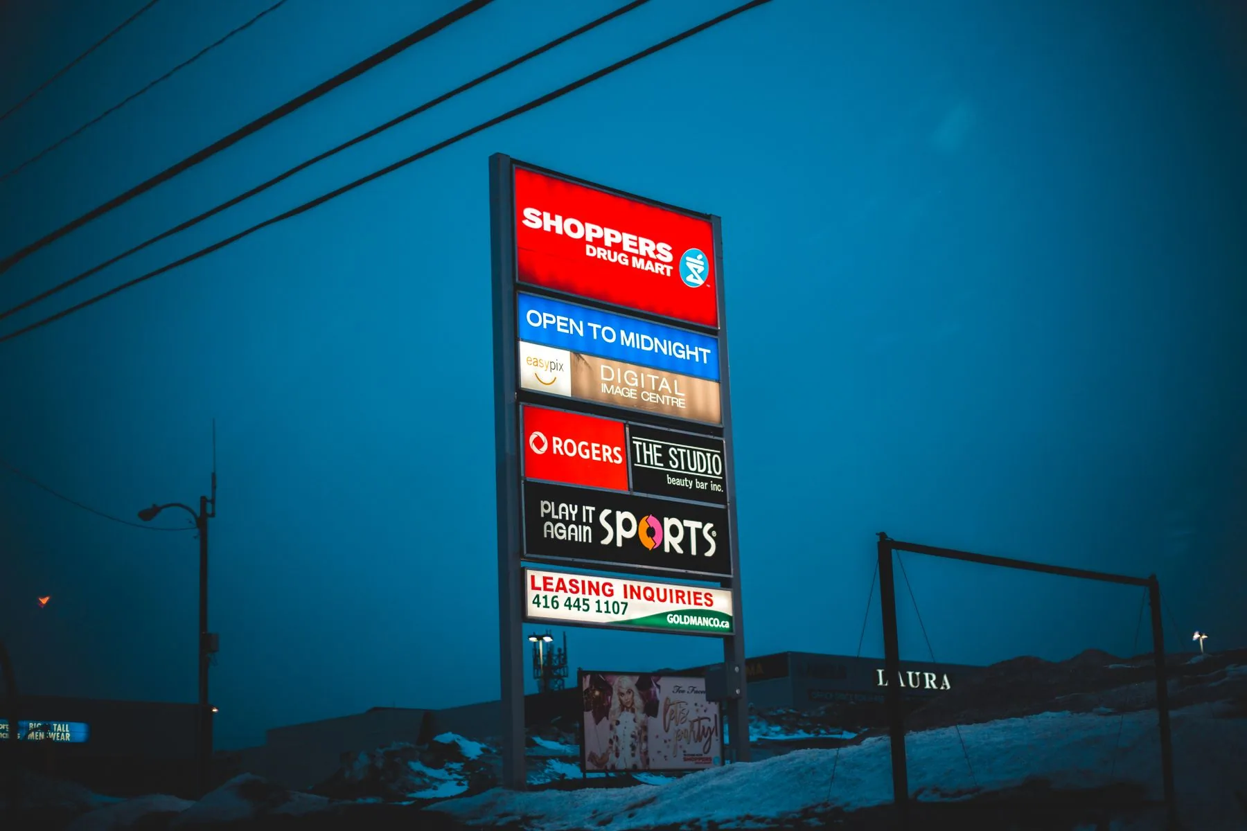
Attracting attention and supporting conversion are the display's first jobs
Peak brightness is selected for ambient conditions; curved, cylindrical and custom shapes can follow the store layout. Remote content delivery can integrate with queue, promotion and membership systems, subject to the project design.
What happens between signal input and display
The diagram below explains the solution boundaries and on-site acceptance checks. It shows the equipment and protocols at each layer and how failover is handled.
← Swipe horizontally to view the full architecture →
Six engineering capabilities that shape the viewing experience
Parameters are defined in the technical appendix and checked against project conditions during acceptance. Capabilities shown here are illustrative.
Wireless display and millimeter-wave backhaul
Use wireless endpoints only when site conditions support them. Assess link encryption, channel, obstructions and interference, and retain a wired option.
Frame-level synchronization · Genlock
A unified network timebase keeps all decoding nodes aligned to the same frame boundary. Fast-moving images remain synchronized across screens without tearing or misalignment, and camera footage shows no scan lines.
Low-latency encoding and decoding
Optional light-compression processing preserves 4:4:4 chroma sampling. End-to-end latency is measured on site for the selected equipment, network and content; conferencing and command scenarios are confirmed in acceptance records.
Flexible windows · roaming · overlays
Define window position, size and layer; move content across screens and overlay picture-in-picture. Group windows for coordinated control and reset layouts with one action, independent of physical panel boundaries.
End-to-end redundancy
Use primary and standby control servers, dual network links and dual node power supplies. Failover time depends on equipment, network and policy; exercises are carried out and recorded in an approved site window.
Unified visual control
Touch consoles, tablets and web browsers provide a consistent interface. Scenario layouts, permission levels, operation audits, equipment records and maintenance tickets are managed on one platform.
From the initial survey to ongoing operations, all six stages have defined deliverables
Each phase has defined documents and acceptance criteria, with traceable progress and ownership. The schedule below is a reference for installations under 30 m² in standard conditions.
Requirements survey
Measure dimensions, viewing distance, ambient light, load capacity and low-voltage conditions on site, and confirm whether reversible installation is feasible.
1–2 daysSolution design
Display selection, location and structural drawings, system architecture, power and network plans, visualizations and budget list.
3–5 daysEquipment preparation
Confirm the equipment list, coordinate supply, inspect deliveries and complete pre-installation integration. Timing depends on selection and supply-chain confirmation.
7–15 daysOn-site installation
Steelwork and display installation, power and low-voltage cabling, node deployment, network configuration and site preparation can be scheduled at night.
3–10 daysCommissioning and acceptance
Calibrate color and brightness consistency, correct geometry, run integration and load tests, train operators and hand over documentation.
1–3 daysMaintenance service
Remote monitoring and alerts, spare-parts coordination, inspections, software upgrades and annual recalibration are provided as agreed in the contract, with response windows recorded in the service terms.
Long-termWhat you receive when you work with us
More than a screen: a display system that can be tested, handed over and expanded, with a clearly accountable team when issues arise.
One accountable team, not four separate vendors
One team coordinates design, displays, transport, control, installation and operations through handover. This gives clients a clear contact for issues instead of being passed between display, installation and network vendors.
Transparent equipment and structural configuration
Itemize display, node, structure, installation and service configurations and prices, with supply relationships and delivery boundaries documented in the plan.
Manageable schedule, with work planned around ongoing operations
Standardized components can be prepared in advance, with site work planned to minimize wet trades. Night and holiday work can be arranged; some meeting-room projects may be completed over a weekend for use on Monday, subject to site conditions.
Verifiable reliability, not a verbal promise
Complete continuous-operation, load and redundancy failover tests against the project technical appendix, record the measurements and review each item at acceptance.
Training and documentation included in handover
Handover includes on-site training, illustrated manuals and operating guides. Administrators can arrange windows and call up scenarios according to their permissions.
An expandable architecture that avoids rebuilding from scratch
Add screens, signal sources, nodes or functions incrementally. Expansion is planned around ports, network and display conditions, with confirmed equipment reused where suitable.
From equipment selection to integration testing, delivery boundaries are documented in the plan
The image shows illustrative equipment and production-line scenes. Yuqi coordinates display selection and supply, on-site installation and integration testing; brands and configurations follow the project design.
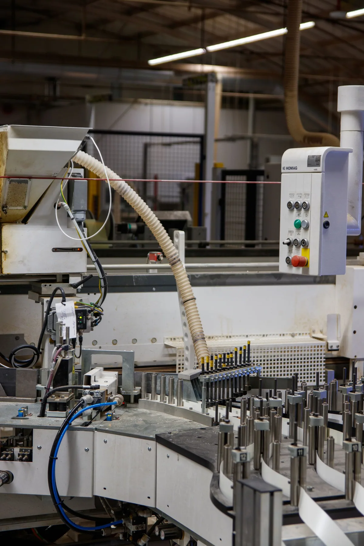
The proposal lists equipment brands and batches, interfaces, structural materials and test records. Site photos are illustrative and do not represent a Yuqi-owned production line or credentials.
Experience helps us anticipate issues before they arise
Insufficient load capacity, a full low-voltage riser, restrictions on hot work or a structural column blocking sightlines should all be addressed during design.
Six common questions before purchase
How is wireless-link reliability assessed for a project?
Can latency support video conferencing and real-time command use?
How do we choose between fine-pitch LED and an LCD video wall?
Can we reuse our existing displays or matrix?
How long will it take? Can work proceed while the venue remains open?
How are warranty and maintenance handled? Can we contact you after the warranty ends?
Survey first, then design
We first review dimensions, viewing distance, ambient light, load capacity and network conditions, then propose equipment, system architecture, installation boundaries and itemized pricing.