
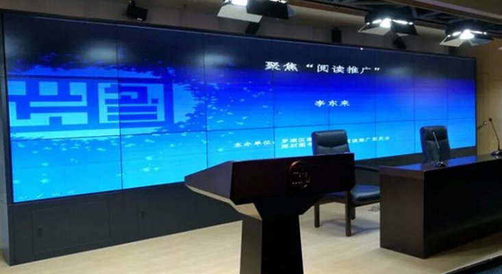
01
Start with the complete display path
The distributed video wall starts with source and control requirements, then validates synchronization, display quality and on-site use.
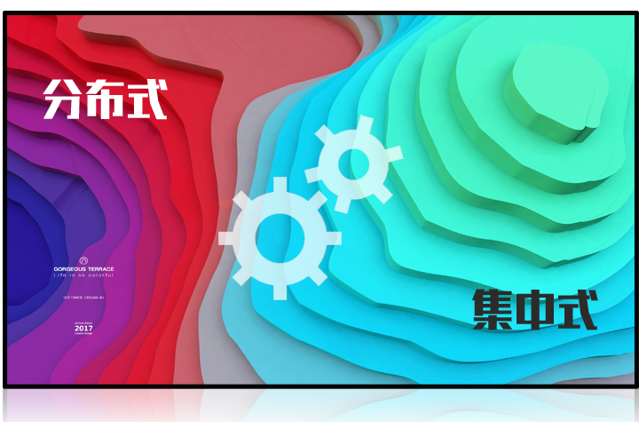
System redundancy
The source material covers centralized, distributed and combined backup arrangements to define system resilience.
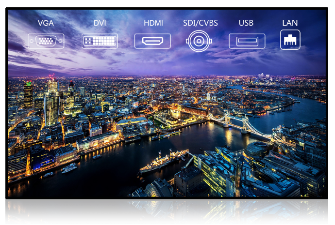
Multi-source signal input
The current specification includes IP, HDMI, DVI, VGA, YPbPr, CVBS and USB inputs, as well as RTSP and ONVIF IP streams.
Synchronized display
Digital signal synchronization, edge enhancement and video-wall composition determine the final image quality.
02
Clarify the path from input to processing to output
A seamless video wall is more than a set of panels: signal interfaces, synchronization, IP streams, matrix control and display units form one path.
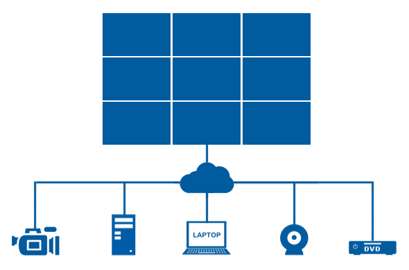
Multiple inputs
Check the required IP, HDMI, DVI, VGA, YPbPr, CVBS and USB connections against the available source material.
Digital synchronization
Synchronized signal processing helps avoid visible timing differences between decoded network images.
IP streams and matrix
Confirm RTSP and ONVIF stream support and hybrid-matrix requirements against the actual number of sources.
Display and installation
The display units, mounting method and site application together define the delivery boundary.
03
Verify capabilities against the display result
The technical features in the original material become checks that can be evaluated before implementation and on site.
Synchronization and composition
Check whether images remain synchronized across panels and whether edge areas meet display requirements.
Decoding and protocols
Confirm interfaces, protocols and decoding modes against actual signal sources.
Redundancy and stability
Define when centralized, distributed or combined backup arrangements apply.
Content and scenarios
Use real presentation content to check aspect ratio, window layout and operating mode.
04
Select mounting methods with site constraints in mind
The original material describes several installation methods. Structural support, cabling and maintenance access must be checked together.
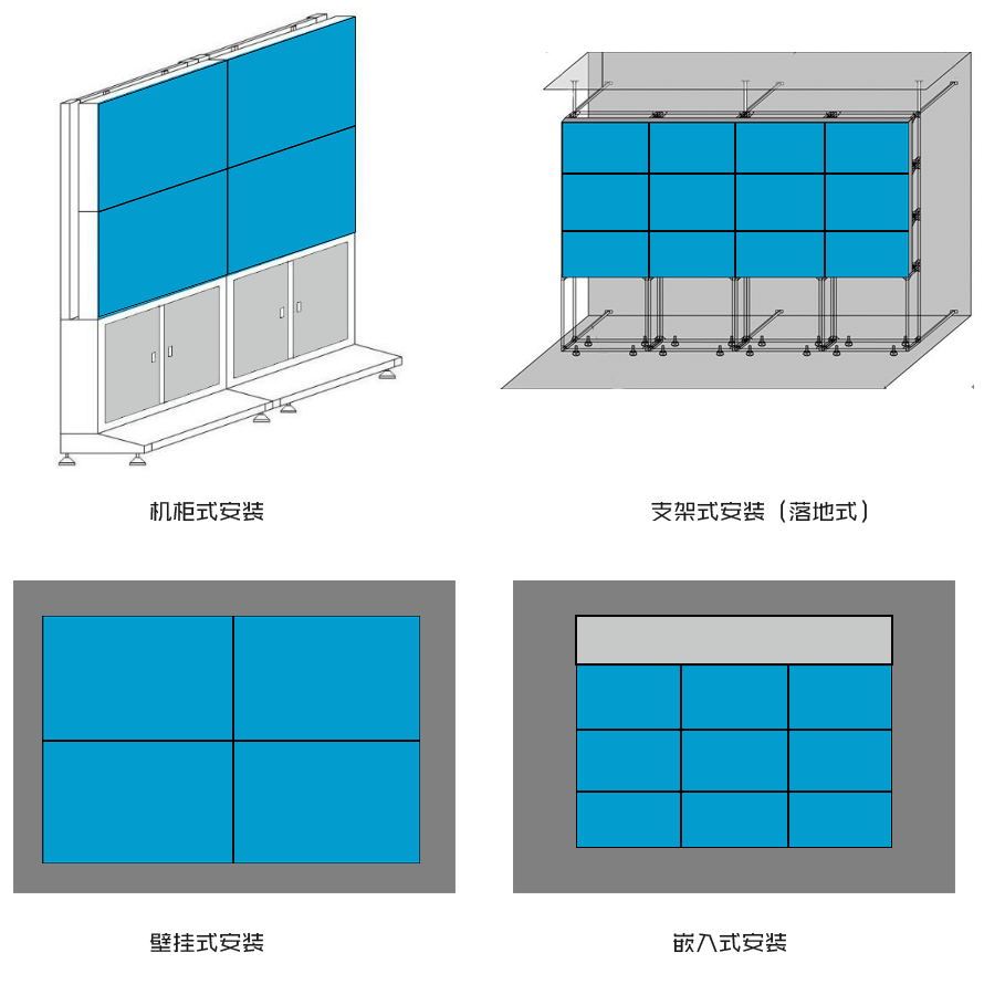
Cabinet installation
Define equipment boundaries and maintenance access for a cabinet-based display system.
Floor-standing supports
Confirm the available floor area, structural load and arrangement of display units.
Wall-mounted or embedded
Reserve mounting, cable routing and service space once the building interface is confirmed.
Scenario validation
Test the viewing result using actual meeting, exhibition or monitoring content.
05
Product material and application settings
Unit appearance, interfaces, mounting options and application examples remain in the original material. Representative images provide a quick overview before the full technical copy.
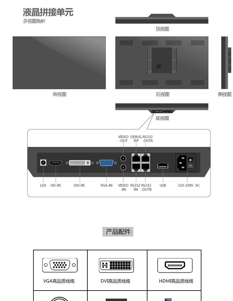
Units and interfaces
Review the physical units, input interfaces and structural details recorded in the product material.
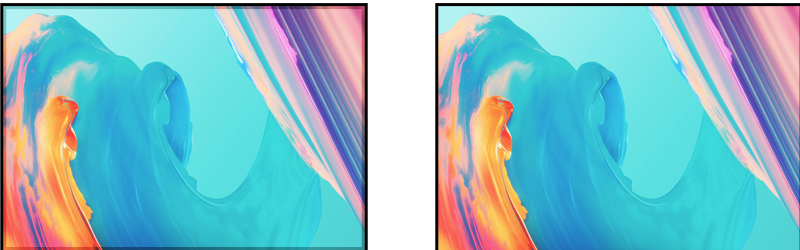
Content and windows
Use actual content to confirm aspect ratio, window layout and display method.
On-site applications
Application images help evaluate the spatial and operational relationship of the display system.
Source material
Current technical material
The complete page copy and technical images are retained below for detailed review.
Open the complete current Page content
Why choose this distributed video-wall system
System redundancy
The source describes centralized, distributed and combined backup arrangements for a resilient distributed video-wall system.

Digital synchronization
Digital signal synchronization helps prevent timing differences between images decoded over the network.

Multi-format decoding
The video wall accepts IP, HDMI, DVI, VGA, YPbPr, CVBS and USB sources and can display them on an individual unit.

Progressive edge enhancement
Progressive edge enhancement addresses dark borders between LCD panels.

Hybrid matrix capability
Progressive edge enhancement addresses dark borders between LCD panels.

IP stream access
RTSP and ONVIF IP streams can be connected for decoded video-wall display.

Seamless LCD video-wall units

Seamless LCD video-wall installation methods

Seamless LCD video-wall applications

Factory image gallery


