
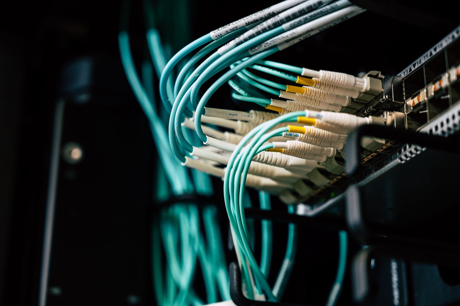
Survey and outlet planning
Review floor plans, levels, rooms, equipment and outlets to define routes and maintenance boundaries.
01 Enterprise structured cabling
Build a reusable connectivity foundation from buildings, equipment rooms and floors to fiber backbones, horizontal copper and information outlets.
Yuqi Intelligent surveys the site, plans outlets and selects/supplies equipment, then completes installation, testing, as-built documentation and expansion support.
Enterprise network paths · Racks and patching · Copper and fiber · Tests and as-built records
01 System logic
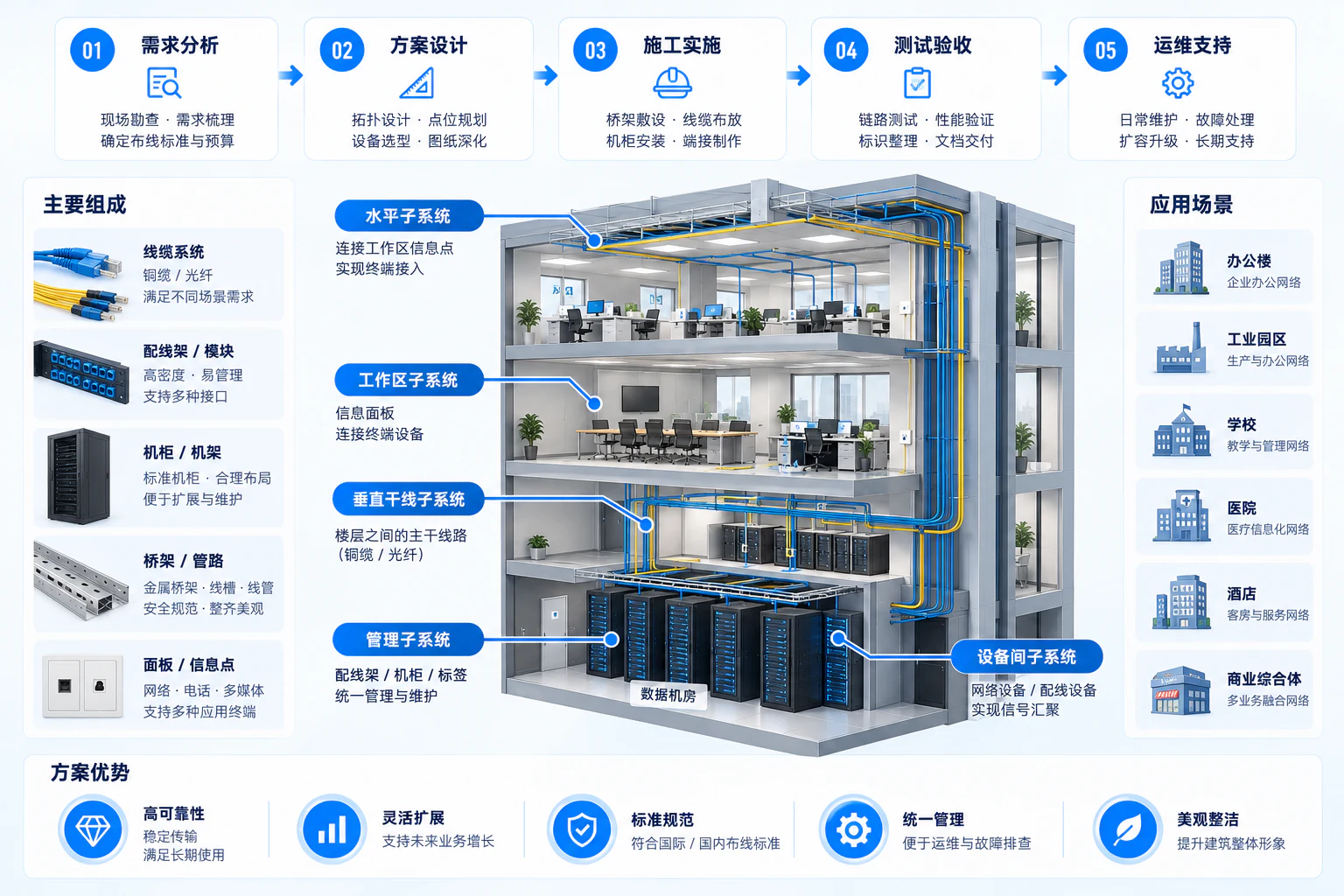
Structured cabling connects spaces, racks, media, terminations and outlets in one architecture. Understand the physical path before planning installation and delivery.
02 Service scope
From site surveys, outlet planning and media selection to supply, installation, termination, identification, link tests and as-built records, Yuqi Intelligent delivers inspectable and maintainable cabling with a clear basis for expansion.
Scope depends on the existing environment, equipment locations, route conditions and agreed services.
Review floor plans, levels, rooms, equipment and outlets to define routes and maintenance boundaries.
Choose copper, fiber, trays, racks and other components by distance, speed and environmental conditions, then supply and install them.
Complete termination, labels, link tests and as-built records to support troubleshooting, expansion and ownership handover.
03 Engineering evidence
Racks, patching, trays and labels turn network relationships into physical infrastructure. Existing cabling and rack imagery provides engineering context rather than reducing the service to small article illustrations.
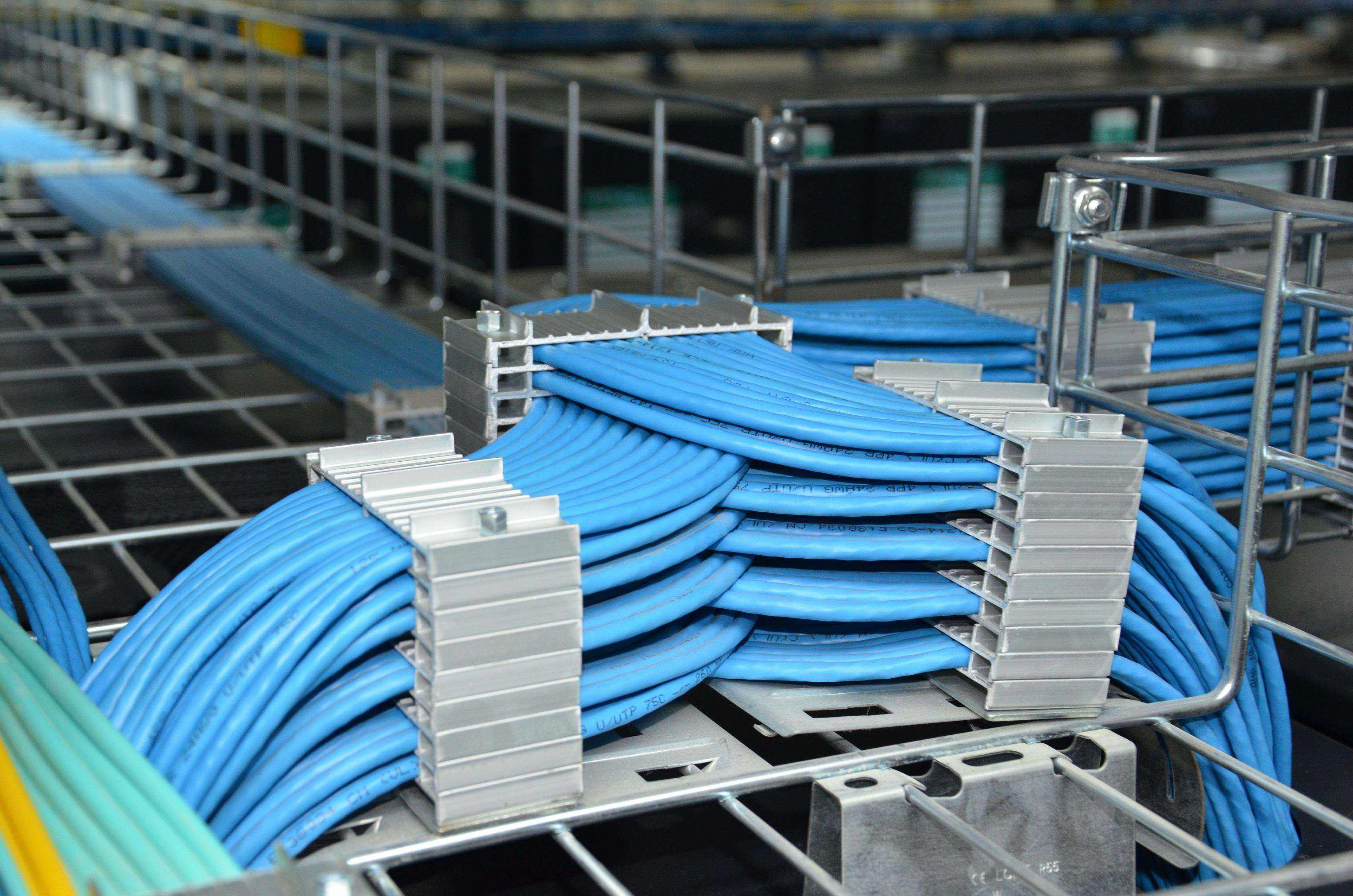

Structured cabling does more than connect devices. It provides a readable site baseline for later maintenance, changes and expansion.
04 Delivery path
Confirm outlets, routes, ports and maintenance space before installation, then complete handover through test records. Stages and scope follow site conditions and agreed services.
Review floor plans, equipment positions, rack locations and installation conditions.
Define media, topology, capacity, routes and expansion reserves.
Install, terminate, patch, label and organize the site.
Hand over test results, link inventories and as-built records.
05 Handover baseline
Record outlets, racks, patching and end-to-end mappings.
Trace links between racks, patch panels and physical outlets.
Support later decisions with test results and site-change records.
Keep evidence for troubleshooting, changes, expansion and ownership handover.
06 Next discussion
Share building layouts, equipment-room conditions, outlet plans or current link problems so we can assess the practical scope.