Architecture view

System relationships

  • 01 System boundary
  • 02 Relationship map
  • 03 Interface dependencies
  • 04 Implementation and acceptance

02 / System integration and infrastructure

Enterprise System Integration

Bring structured cabling, networks, communications, security, server rooms and business systems into one implementable architecture, solving the gaps between individually working systems.

Enterprise server racks, network connections and system integration environment
The outcome of system integration is a shared view of equipment, links, data and operating ownership.
Integration objectsEquipment / networks / data / workflows
Technical focusInterfaces / topology / migration / acceptance
Handover resultShared view / testable / maintainable

01 / Problem profile

System integration is not about having equipment; it is about making the equipment work together

During expansion, relocation or renovation, the hard part is usually not the purchasing list. It is the connections, interfaces, data and ownership between systems. Cabling may be installed and network devices may be online, but without shared topology, naming, access and acceptance evidence, operations still depend on people searching by experience.

Enterprise system integration considers telephone communications, LANs, broadcast, video surveillance, access control, parking, building control, server rooms and structured cabling as one technical chain. The aim is not to turn every system into one product, but to define boundaries, uplinks, data flows and maintenance entry points.

This makes resources easier to plan, reduces duplicated build work, gives troubleshooting and change handover a shared baseline, and lets future equipment or office areas extend from the existing architecture.

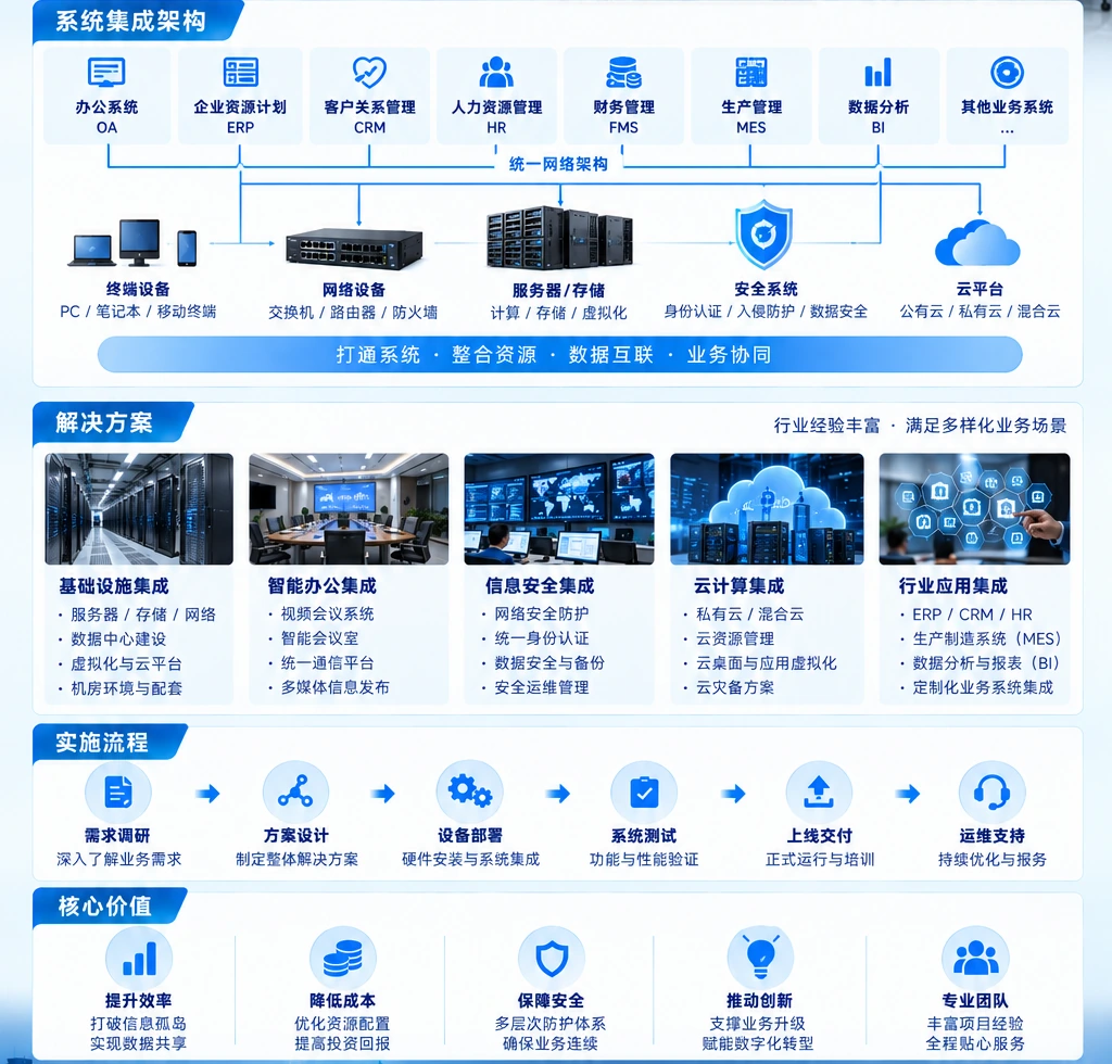
Enterprise system integration map across servers, networks, data and security
Place servers, networks, data and security into one relationship that can be checked.

Three core integration gaps

Reduce recurring delivery, connectivity and handover problems to three core gaps before sequencing the technical work.

01

Each system works alone, but systems do not coordinate

Equipment and software go live separately without clear interfaces, interaction conditions or data exchange rules.

Solves: define boundaries and interfaces before joint commissioning.
02

Drawings, site conditions and live connections do not match

Construction changes, port changes and equipment replacements are not reflected in the records, so maintenance teams cannot trust the drawings.

Solves: make topology, outlets, ports and labels part of handover.
03

Resources are invested, but operations and handover are not closed-loop

Servers, storage, networks and room conditions are not assessed together, while testing records, configuration lists and ownership boundaries are missing. Expansion, migration and later incidents then become reactive decisions.

Solves: establish a resource baseline and complete technical and operations handover with verifiable records.
04

Access and security boundaries are missing from integration design

The network is connected, but identity, access rights, system zones and audit logging are not defined together, blocking valid access while exposing unintended paths.

Solves: include identity, access, segmentation and audit in architecture, commissioning and acceptance.

02 / Architecture

Map the relationships before choosing equipment, interfaces and delivery order

An implementable integration plan answers four questions: what objects exist, how they connect, how data and access move, and who handles incidents. The architecture diagram is not decoration; it is the working baseline for procurement, construction, configuration, testing and operations.

In practice, network platforms, hardware systems, applications, intelligent low-voltage systems and information security are not unrelated packages. They connect through links, interfaces, authentication, logs and operating rules; a missing definition at any layer pushes the problem downstream.

System integration, network platform, hardware and information security relationship diagram
Use one relationship map to confirm the integration boundary across networks, applications, hardware, security and site systems.

Four relationship layers

Trace the chain from site connectivity to business operations

A system needs to be read in its relationships to understand which links, access rules, applications and operating actions a device change will affect. These four layers form one path from facility conditions to business outcomes.

A

Facility and connectivity layer

Structured cabling, racks, patching, links and network exits determine whether equipment can connect reliably.

B

Network and access layer

Switching, routing, wireless, authentication and security boundaries determine who can reach which resource.

C

Compute and data layer

Servers, storage, virtualization, backup and capacity relationships carry business workloads.

D

Application and operations layer

Business systems, monitoring, logs, tickets and ownership make the integrated environment operable.

03 / Technical scope

Break the integration boundary into five technical views that can be checked

The scope is confirmed around the business context, existing equipment and delivery goals. These five technical views cover the main decisions from site connectivity to business operations; not every project needs all of them at once, but they prevent interfaces and ownership from being missed.

Traditional low-voltage integration starts with communications, networks and site systems. Modern enterprise environments also need servers, storage, virtualization, data, access and security. Putting them in one scope table prevents a project from delivering visible equipment while missing the relationships required for operation.

Enterprise data-center server racks and infrastructure aisle
From racks and links to the operating environment, the technical scope must land on infrastructure that can be implemented and checked.
01

Structured cabling and network foundation

Plan outlets, copper and fiber, racks, patch panels, switching, routing, network exits and expansion paths.

Outlets / links / topology / labels
02

Communications, security and site systems

Connect interfaces and interactions across telephony, broadcast, surveillance, access control, parking, building control and meeting spaces.

Interfaces / interactions / access / logs
03

Servers, storage and computing resources

Confirm compute, storage capacity, virtualization relationships, backup protection and application dependencies before equipment goes live.

Capacity / dependencies / protection / migration
04

Information security and access control

Place segmentation, identity, access rights, boundary protection and audit requirements into the system interaction model.

Segmentation / identity / protection / audit
05

Monitoring, records and operating entry points

Define alerts, logs, asset records, contacts, maintenance windows and escalation paths so the project remains manageable after handover.

Monitoring / records / contacts / changes

04 / Connectivity layer

The connectivity layer determines whether systems can work together

Connecting equipment is more than plugging in a cable. Ports, addresses, links, capacity, segmentation, authentication and access policies determine whether data reaches the right system and whether an incident can be narrowed quickly.

Before delivery, name and number links and interfaces by equipment, area and business use. During delivery, commission end to end against the topology and configuration. At handover, write actual ports, addresses, policies and test results back into the records.

01

Traceable links

Every link can be located by number from rack and patch panel to switch port.

02

Verifiable interfaces

Connectivity, throughput, redundancy and failover tests confirm that interfaces work beyond a single point.

03

Manageable access

Identity, segmentation, permissions and audit define the access boundary and reduce unintended reachability.

Switch ports with blue and yellow fiber network cabling
Live connections must correspond to topology, port labels and test records.

05 / Resource layer

Plan servers, storage and computing around business dependencies

Once integration reaches the resource layer, the question shifts from whether equipment can be racked to how workloads will run. Servers, storage, virtualization, backup and networks have capacity, performance, availability and recovery dependencies that need to be confirmed together.

This is the difference between integration and equipment purchasing. Purchasing shows that resources were acquired; integrated delivery also explains allocation, application access, fault isolation, expansion headroom and post-migration ownership.

01

Capacity baseline

Inventory CPU, memory, storage, network and rack space as a comparable baseline before expansion.

02

Application dependencies

Confirm dependencies between applications, databases, file services, identity and external interfaces.

03

Protection and recovery

Include backup, recovery testing and continuity requirements in migration and operations design.

06 / Delivery and handover

From survey to acceptance, every step leaves evidence for the next

System integration often crosses building, network, equipment, software and operations teams. The delivery sequence needs to connect site conditions, interfaces, configuration changes and business validation, so missing test criteria are found before construction is complete.

  1. 01

    Survey and inventory

    Review the building, server room, network, equipment, systems and existing records; mark gaps and conflicts.

  2. 02

    Architecture and interface design

    Define topology, equipment relationships, interfaces, access, capacity and delivery boundaries.

  3. 03

    Phased implementation

    Install, configure, commission and control changes by area, system or migration window.

  4. 04

    Test and remediate

    Verify connectivity, access, performance, redundancy, alerts and business scenarios; close the issue loop.

  5. 05

    Records and operations handover

    Hand over topology, configuration, assets, ports, tests, contacts, maintenance windows and next-step recommendations.

Server racks and on-site operations handover
Configuration, ports, status and maintenance ownership are confirmed together at handover.

07 / Handover records

Handover includes a technical baseline that can keep being used

The long-term value of integration depends on whether the environment remains understandable, searchable and changeable after delivery. Records are not an appendix written at the end; they are operating assets that let procurement, expansion, troubleshooting and change follow the same logic.

01
Architecture and topology

Keep system boundaries, equipment relationships, link paths, network zones and key interfaces.

02
Assets and configuration

Record equipment, ports, addresses, versions, configuration, owners and change status.

03
Testing and remediation

Save connectivity, performance, access, redundancy, alert and business validation records.

04
Maintenance and upgrades

Describe contacts, maintenance windows, spares, upgrade paths, rollback conditions and expansion advice.

FAQ

Frequently asked questions

Confirm the service boundary and current conditions before deciding delivery scope and ongoing support.

What is the difference between system integration and equipment purchasing?

Purchasing answers what and how much to buy. Integration also answers how systems connect, how they are verified, how they operate and who owns them. Architecture, interfaces, configuration, testing and handover records are part of the scope.

Do we need integration if we already have networks and servers?

Not necessarily. Start from the existing topology, ports, resources, dependencies and operating issues; fill the missing relationships and records before deciding the upgrade or expansion scope.

Can integration support future expansion and migration?

It can, if capacity, ports, network paths, interfaces and maintenance space are reserved during design, with migration windows, validation criteria and rollback conditions in the delivery plan.