

Systems integration / Low-voltage systems
IT Integration and
Low-Voltage Systems
Yuqi Intelligent provides surveys and detailed design, equipment selection/supply, cabling, installation, configuration, integration and acceptance, coordinating networking, compute, security and meeting systems.
01Clarify the problem first
Powered-on equipment does not prove a usable system.
During construction, relocation or upgrades, different teams may handle networking, equipment rooms, cameras, access, meetings and endpoints. A site can look finished while users face mismatched locations, unowned permissions, disconnected meeting equipment and unclear fault boundaries.
Integration first defines cabling, access networking, corresponding platforms and operating ownership for each endpoint, then connects compute/storage, permissions and maintenance in a verifiable diagram. Work involving Structured Cabling, Network Access or Enterprise Systems Integration is coordinated around actual interfaces and construction boundaries.
Separate installations leave interfaces unowned
Equipment lists, network ports, platform accounts and site windows lack one shared baseline.
Connections work, but workflows remain broken
After endpoints go online, permissions, meetings, video and office workflows still need testing in real scenarios.
Handover relies only on site memory
Without location/topology, configuration, labels, tests and operations records, later adjustments require guesswork.
02Animated system relationships
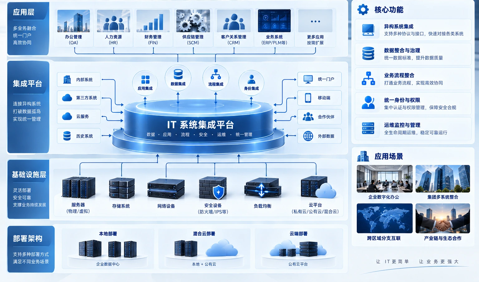
Endpoint access and platform coordination
Office, meeting, access and video endpoints reach their platforms through cabling and PoE/access networks. Compute/storage provide resources, with permissions and operations spanning layers. Verify interfaces and conditions before phased site integration.
Three endpoint groups reach their platforms through cabling and PoE/access networks. Compute/storage provide resources; permissions and operations are cross-layer management relationships. Confirm actual interfaces and operating conditions.
The diagram explains implementation boundaries. Integrate equipment, platforms and protocols after confirming inventories, open interfaces and site conditions.
03Engineering and IT services from Yuqi Intelligent
From locations and equipment to an acceptable delivery.
Organize work packages by site conditions, coordinating wiring, equipment, networks and platforms under clear interfaces and responsibilities.
Site surveys and detailed location planning
Review floor plans, racks, endpoint counts, routes, power and installation windows to define locations and boundaries.
Equipment inventory, selection and supply
Prepare inventories, configuration recommendations and quotations by usage, interfaces, capacity, power and maintenance.
Racks, patching, fiber and copper
Organize racks, patch panels, fiber, copper, labels and terminations into traceable, testable physical links.
Switching, wireless and access networks
Plan switching, wireless, PoE and segmentation, confirming coverage and management boundaries against site conditions.
Cameras, access control and meeting spaces
Connect camera, access, meeting and office endpoints to their respective platforms, coordinating configuration against open interfaces and actual scope.
Configuration, testing and handover
Complete platform configuration, interface coordination, link/function tests, labels, as-built records and training.
04Phased implementation and customer handover
Every stage leaves evidence for the next.
Start with site surveys and progress through inventories, installation, configuration, integration and acceptance. Qualified partners handle regulated fire-safety, electrical and other specialist construction as required.
Survey and detailed design
Review spaces, locations, existing systems and construction conditions to decide what to build, upgrade or retain.
Inventory and implementation preparation
Confirm equipment, ports, media, racks, power coordination and phased windows, with responsibilities and acceptance criteria.
Phased installation and integration
Install and configure links, networks, endpoints and platforms in phases, verifying interfaces and conditions before integration.
Testing and customer handover
Hand over and train using location/topology records, configurations, link/function tests and as-built/operations documentation.

05Customer deliverables
Hand over system relationships, not just equipment.
Deliverables follow actual scope and acceptance conditions. For network expansion, link management or server resources, coordinate with Enterprise Networking and SD-WAN and document change ownership in operations records.
- Location inventory, system boundaries and topology
- Equipment configuration, port and link labels
- Link/function tests and issue-resolution records
- As-built documents, support channels and training records
06Frequently asked questions
Clarify boundaries and acceptance criteria first.
Why is integration needed when specialists procure separately?
Separate purchasing does not establish site usability. Without aligned locations, power, networking, interfaces, permissions and responsibilities, equipment may go online independently but fail to support business workflows.
Can both new builds and upgrades start with a survey?
Yes. New builds focus on spaces, locations and reserves; upgrades inventory existing links, equipment, platforms and windows before choosing retention, replacement or phased changes.
How are different brands and existing devices coordinated?
Check compatibility against interfaces, platform capabilities, permissions and project boundaries before configuration and site integration, coordinating vendors or qualified partners where necessary.
Can existing equipment and cabling remain?
Inventory locations, links, device health and construction conditions. After testing and risk review, retain usable components and replace or adapt those that cannot meet new goals, documenting boundaries.
What records and support are available after handover?
Provide agreed location/topology, equipment configuration, port/link IDs, link/function tests and as-built/operations records, with further change, troubleshooting and training support discussed as needed.
Next step / FIELD REVIEW
Start with a location plan or a site issue.
Share space, network and endpoint conditions for offices, campuses, relocations or upgrades to define surveys, implementation and handover.