
Run an office network project as a controlled sequence: business scope → site survey → approved design → staged configuration → installation and cutover → layered acceptance → operations handover. A switch showing an active link or a laptop reaching the internet proves only a small part of the service. Each acceptance item needs a defined endpoint, test method, pass criterion, owner, and retrievable evidence. Choose the topology, redundancy, and test limits for the actual site and contract rather than copying a generic diagram.
Scope: what this checklist covers
This guide is for a new office network, a move, an expansion, or a retrofit. It follows office endpoints through access switching, gateways, wireless access, and the business paths included in the project. Building communications infrastructure, carrier services, structured cabling, electrical work, fire stopping, and other low-voltage systems may involve separate scopes and accountable parties. They need explicit interfaces and acceptance records; a switch configuration cannot stand in for those work packages.
China’s GB/T 50312-2016 standard applies to acceptance of structured cabling systems in new, expanded, and renovated buildings and campuses. It distinguishes construction quality checks, concealed-work inspection, self-testing before acceptance, and completion acceptance. It can be relevant to the structured cabling scope; that does not automatically make every office LAN change, VLAN configuration, or application test part of the same acceptance procedure. Verify the project type, contract, design, and applicable standards before setting the test plan. Standard and official PDF: Guangdong Communications Administration
Guangdong’s 2025 trial implementation guide for building communications infrastructure covers planning, implementation, acceptance, and filing for communications infrastructure fitted to new, renovated, or expanded buildings in Guangdong. Apply it when the project and parties fall within its stated scope. Do not treat it as a universal checklist for every internal office-network retrofit. Official guide: Guangdong Communications Administration and Department of Housing and Urban-Rural Development
1. Agree scope and acceptance before the survey
Bring business owners, IT, facilities or property management, the installer, and the operations team that will receive the network into one scope review. Otherwise, equipment may be installed while nobody owns the carrier handoff, building cabling, firewall path, or server-side test.
| Confirm | Record | Why it matters |
|---|---|---|
| Users and endpoints | Floors, departments, desks, meeting rooms, printers, phones, visitors, APs, and any in-scope cameras or IoT | Produces a point and service inventory instead of guessing port count from headcount |
| Required paths | Internet, headquarters VPN, file service, ERP, printing, meetings, guest access, and other named services | Defines the source, destination, protocol or port, and service owner for acceptance |
| Project boundary | New cabling, reused links, equipment supply, carrier service, firewall, WLAN, endpoint changes, and who owns each | Exposes cross-team dependencies and exclusions |
| Operating goals | Service windows, acceptable interruption, required link or device redundancy, and recovery target | Determines design complexity and which failure tests are appropriate |
| Pass criteria | Points, link class, configuration baseline, allowed paths, coverage or capacity measures, and evidence format | Prevents a last-minute argument over what “working” means |
| Change control | Change owner, approver, notifications, window, rollback trigger, and person able to restore | Makes it possible to stop or reverse a risky change |
“Internet access works” validates one path. Office networks can also have internal applications, file services, guest isolation, printing, wireless authentication, and inter-segment policies. Mark each as included or excluded, and identify who supplies test accounts, target addresses, and business sign-off.
2. Survey the physical environment and the existing network
The survey is more than a rack photo. Map each floor’s information outlet, patch-panel position, switch, uplink, rack space, and label. Convert observations into work items with an owner and due date.

Caption: Photographer panumas nikhomkhai, Pexels photo ID 19226354. This is licensed stock imagery used only as context; it does not show a Yuqi employee, customer, or the project described here. See the [source and license record](../来源与版权记录.md).
Room, rack, power, and access
- Rack conditions: location, available rack units, depth, load rating, front and rear service clearance, locks, and key control. Check whether new equipment will obstruct existing equipment or maintenance access.
- Power and UPS: identify available outlets and circuits, plug types, redundant power-feed arrangements, and UPS headroom. The presence of a UPS does not prove runtime. Have the responsible facilities or electrical professional verify capacity and any power work.
- Ventilation and environment: note airflow direction, cooling operation, filters, and enclosure conditions. Check temperature, humidity, and clearance against the exact equipment manuals and site design; do not apply a model-free temperature rule.
- Grounding and safety: inspect grounding, cable restraint, sharp edges, trip hazards, and work-zone separation. Electrical, fire-stopping, and building work belong to the parties responsible for those scopes under applicable requirements.
- Site access: record sign-in, permitted work hours, noise or power restrictions, property approvals, ladders or lift requirements, and other work permits that apply.
Cable routes, outlets, and existing equipment
- Point mapping: sample and verify outlet label → patch-panel port → switch and port → endpoint. Mark unlabelled, mismatched, obstructed, unused, and business-critical links.
- Cable pathways: inspect trays, conduits, shafts, bend radius, separation from electrical or interference sources, floor penetrations, fire stopping, and future service access. Where a hidden-work check is required, retain the inspection record and images before the route is closed.
- Copper and fiber: record media type, category, length or distance, connector, fiber type, and existing test report. Verify transceiver compatibility, wavelength or media, link budget, and vendor support against the equipment and cable documentation.
- Current-state inventory: device model, serial, software or firmware, entitlement, configuration backup, used ports, uplinks, addressing, VLANs, routing, DHCP, DNS, firewall policy, and operations contacts. Store configurations only in an approved controlled location; keep passwords and keys out of ordinary handover files.
- Cutover constraints: identify services that must stay online, protected devices, temporary paths, carrier or headquarters dependencies, and the person responsible for each dependency.
3. Turn survey data into a design that can be installed
Design inputs should include the point schedule, port and link list, current logical diagram, business paths, device capability and entitlement, rack and power conditions, addressing and security boundaries, and acceptance sheet. The installer should be able to answer: where a device goes, what each port connects to, what the port does, where its address comes from, which destinations are allowed, and how to restore service after a failed cutover.
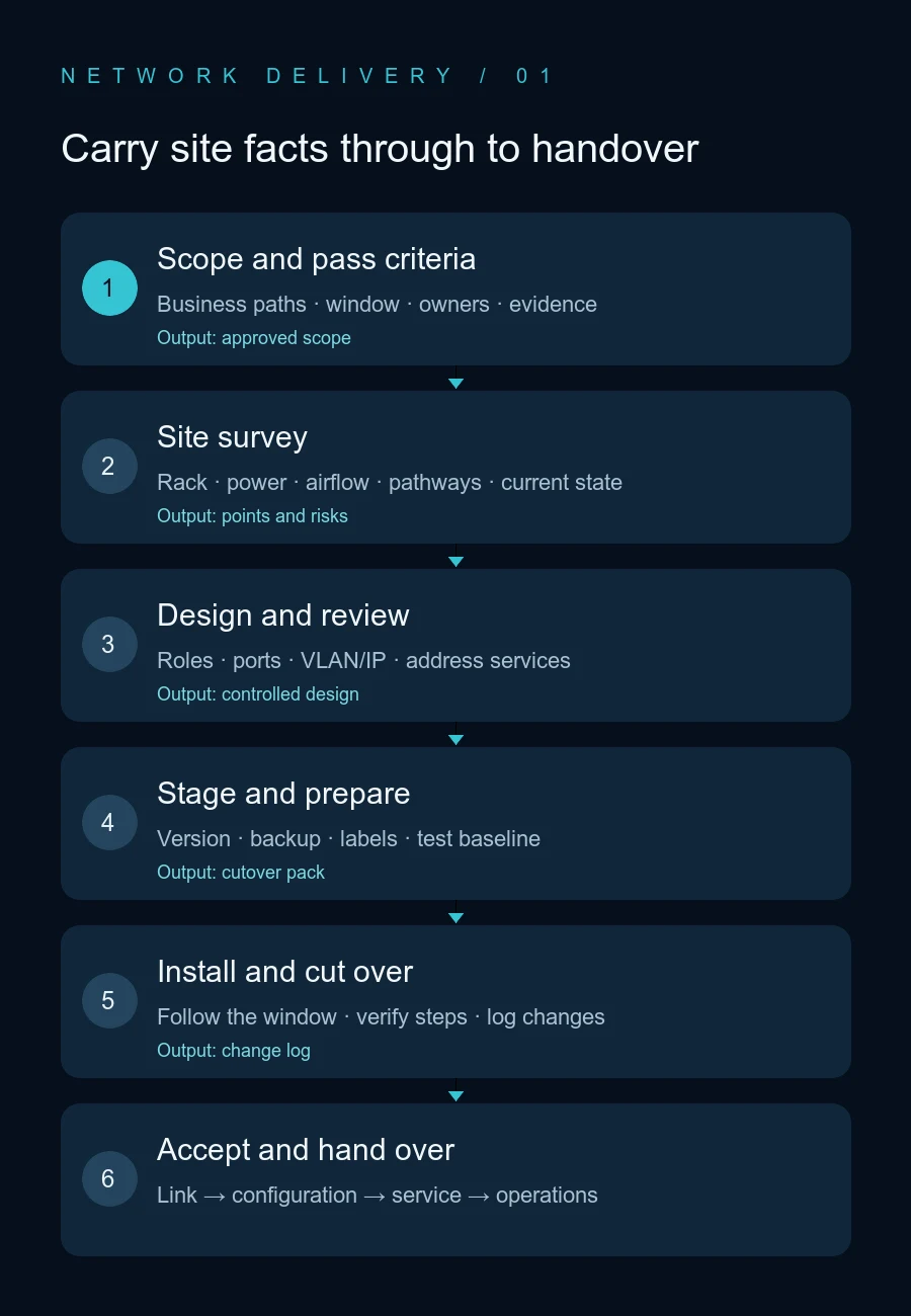
Caption: The stages help assign work and evidence. They do not require every project to use the same equipment tiers or timeline.
Choose a topology for the site; do not add layers by default
Cisco’s campus LAN guidance describes small, medium-density, and large sites. A design can range from a single access switch to access, distribution, and core modules depending on endpoint scale, link capacity, fault impact, service availability, and the team’s ability to operate it. This is a vendor design reference, not a Yuqi customer configuration, and it does not mean every office needs a three-tier design. Cisco Campus LAN and WLAN Design Guide
Review these items in the design:
- Capacity and growth: count actual endpoints, APs, printers, meeting devices, cameras or access-control systems when in scope, then record spare capacity. Calculate uplinks from concurrent traffic, egress speed, aggregation, and the failure model rather than using a fixed oversubscription ratio as a substitute.
- Ports and links: assign each access port a purpose, speed, PoE need, VLAN, and security policy. Document uplink ports, media, path, aggregation mode, and who configures each end.
- Logical segmentation: list only the networks that the environment actually needs, such as employee, guest, voice, printer, server, management, and IoT. A VLAN separates Layer 2 domains; routing, firewall, and access-control policy determine what may cross between them.
- Core services: confirm DHCP scope or relay, default gateway, DNS, NTP, identity, address reservations, retention, and log source. Record who owns each service and approves new segments.
- Security and management: define management addresses and allowed sources, administrator roles, protocols, logging or monitoring, configuration backup, and escalation. Include steps to remove temporary management access, default credentials, and temporary firewall rules.
- Redundancy and failure impact: if the business requires dual uplinks, dual power, a stack, or gateway redundancy, show the genuinely separate paths and remaining single points of failure. Also document the added configuration, testing, and support complexity. Redundant devices alone do not prove high availability.
The design is ready for staging only when addressing, VLANs, ports, uplinks, device locations, test targets, change window, rollback, and owners are in a version that the affected parties have reviewed.
4. Stage equipment and cut over with a rollback plan
Stage A: preparation and pre-configuration
- Freeze the approved equipment list, topology, interface schedule, configuration version, and work owners. Confirm model, software compatibility, licenses or subscriptions, transceiver and cable match, PoE budget, rack hardware, and spares.
- Validate baseline configuration away from production: management address, time, logging, roles, interfaces, VLANs or trunks, link aggregation, routing, DHCP relay, and security policies. Where equipment is available, use a lab or isolated environment to check boot, software version, and critical links.
- Export current configuration and required state. Check that the backup is readable and stored in an approved location. Prepare old-to-new port mapping, work sequence, labels, rollback steps, and contact list. Never paste secrets or customer data into a public log.
- Capture the pre-change baseline: critical-device reachability, uplink state, interface errors, representative service tests, egress or tunnel status, and existing incidents. If the baseline is already unhealthy, assign ownership before deciding whether to proceed.
Stage B: install and inspect in controlled segments
- Match each arriving device to the equipment list, including model, serial number, accessories, and physical condition. Verify rack, power, ventilation, and grounding conditions before mounting and powering equipment.
- Connect patch panels, switches, and uplinks against the point schedule, and label both ends consistently. Clean fiber end faces and check media and polarity according to the applicable procedure. Record the original port before moving a live cable.
- For each device, inspect boot state, fan and power status, alarms, software version, time, and management access; then save the configuration backup. Check only the features used in the approved design: interface state and speed, errors or discards, VLAN or trunk, uplink aggregation, and the selected loop-prevention or routing functions.
- Use an isolated test port to verify address assignment, name resolution, and an approved service. Then migrate a representative user group or service path according to the approved sequence. Change only the planned unit at a time; retain timestamps and logs instead of stacking undocumented fixes.
Stage C: maintenance-window go/no-go
Go before work: the change is approved; users have been notified; required roles are present; configuration and cable maps are available; rollback data can be used; test equipment and accounts are ready; critical out-of-scope services are protected; and enough of the approved window remains.
During the change: log start and finish times and a concise change record; complete one change unit at a time; after each unit, verify management access, uplinks, address services, and the representative business path. Use the observation period and measures defined in the approved acceptance plan.
Stop and roll back if the agreed window is exceeded, a critical path is down beyond the authorized impact, the live configuration differs from the approved version, backup or rollback is unavailable, an unbounded security or addressing issue appears, or the service owner invokes the agreed trigger. The named change owner decides and performs the documented restoration. Do not casually unplug a core link to “test redundancy.”
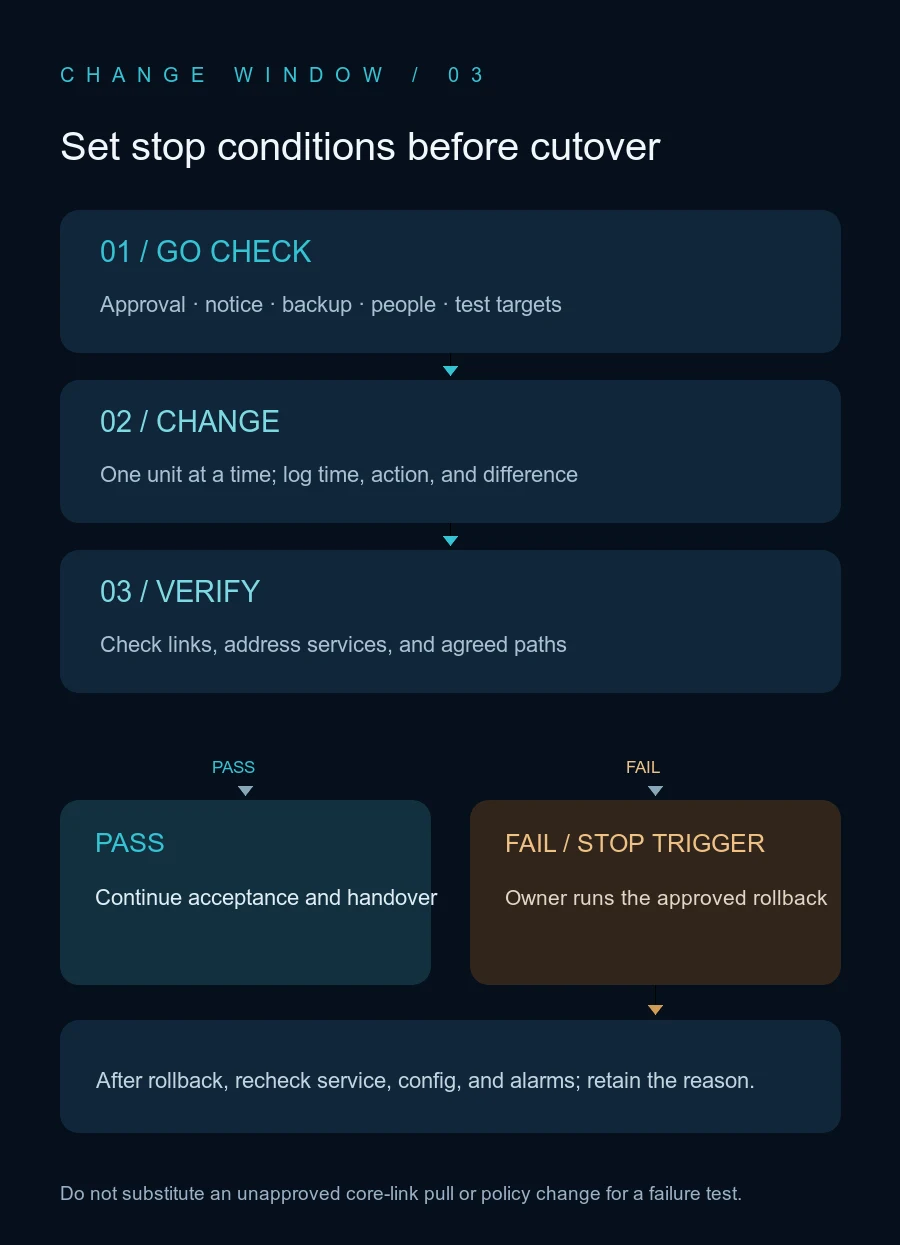
Caption: The rollback branch must name this project’s owner, trigger, and executable steps. The diagram itself is not approval to make a change.
5. Accept in layers, with evidence for every pass
The table is a starting point for agreeing scope, not a universal threshold. Before work begins, define limits, sample size, test endpoints, instrument requirements, retention period, and sign-off owner. Requirements vary by cable category, equipment, service, contract, and standard.
| Layer | What to inspect | Method and evidence | Who defines pass criteria |
|---|---|---|---|
| Room and power | Location, rack units, circuit, UPS or redundant feed, airflow, clearance, labels | Site checklist, device photos, alarms and power status; electrical or fire items by their responsible professional | Owner, design, facilities, equipment manuals, and applicable work requirements |
| Structured cabling | Point mapping, wire map, link-category performance, fiber polarity or loss where applicable | Identify each point; use the correct tester and limits for the agreed scope; retain raw results, instrument details, and status/calibration data | Contract, design, applicable cabling requirements; a link light or basic continuity tester is not certification |
| Switching and ports | Model/version, boot alarms, management, port state/speed, errors, PoE, uplinks | Device output or management record compared with approved device, port, and link schedules | Approved design, vendor specifications, and project baseline; check PoE against actual endpoint models |
| Layer 2 and address services | Access or trunk VLAN, aggregation consistency, address pool, gateway, DHCP relay, DNS/NTP | Test endpoint configuration plus switch, firewall, and server-side logs | IP plan and security policy; expected access list for each segment |
| End-to-end service | Agreed employee, guest, meeting, printer, or application path; allowed and denied inter-segment traffic | From a named source to a named destination, use an approved account and real service action; retain both ends’ logs and timestamps | Service owner defines what successful business behavior looks like |
| Redundancy and recovery | Behavior after failure of an explicitly designed link, device, or egress path | Only during an approved window; simulate the agreed single failure and record convergence/recovery, loss, business impact, and alarms | Contract or service recovery goal and the approved failure scenario; no metric means no claim of meeting one |
| Operations handover | Configuration version, topology, port map, contacts, backups, recovery and change records | Read back the documents and verify scope, version, date, and usability with the receiving team | Operations owner and handover list; deliver secrets only through a separate controlled channel |
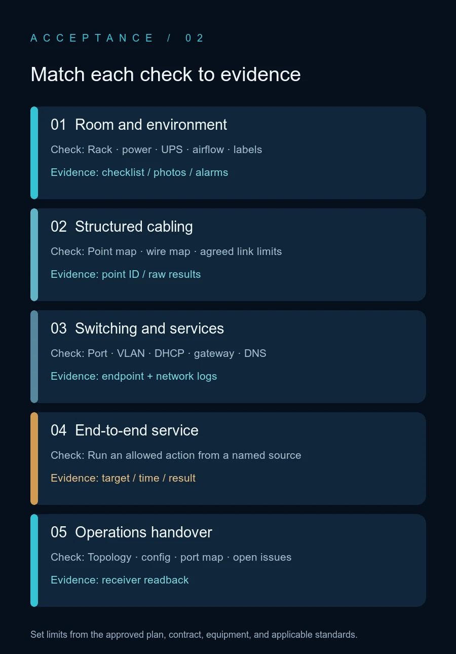
Caption: Each check should identify its physical point, version, and test time. The layers shown do not define fixed pass limits.
Three checks that are often confused
- Cable test: a continuity or wire-map check proves limited physical facts. Qualification or certification against a category limit requires the right instrument, link model, and agreed limit. Keep raw results tied to each point.
- Port is up: an interface state only shows that a link was established. It does not prove DHCP, DNS, routing, policy, or the application path. Check both ends of the link and a permitted service.
- “The internet works”: that proves one endpoint reached one external destination at that moment. It does not replace guest isolation, internal permissions, wireless coverage, capacity, security policy, or recovery acceptance.
For endpoint verification, record the test device, switch port or SSID, IP address, gateway, DNS, time, and target. On Windows, ipconfig /all can show the endpoint lease and DNS settings; nslookup can check name resolution; Test-NetConnection can check an approved server port. Then perform the real business action and compare the result with server or firewall logs. Command output describes one endpoint and path at one time; it cannot prove the entire network passed.
6. Close failures instead of hiding them in “mostly works”
- Give each issue an ID. Record location or point, device and port, time, symptom, impact, test method, raw result, and where to find the photo or log.
- Decide whether the impact is spreading or involves a security or critical service. Pause later cutover steps if needed, notify the owner, and return to a safe state.
- Change one variable under the approved plan. Record the configuration difference, rerun the failed item, and run regression checks on affected paths. “Fixed” without a result is not evidence.
- If unresolved, list the item as open with its workaround, residual risk, owner, due date, and acceptance party. Sign-off may record an explicit exception; an exception is not a PASS.
7. Handover and project closeout
The operations team should receive the final physical and logical diagrams, device and serial inventory, rack and port schedule, outlet-to-patch-panel mapping, IP/VLAN/routing/DHCP/DNS responsibility list, configuration version and controlled backup location, software and entitlement information, original link test reports, cutover log, acceptance sheet, open exceptions, and escalation contacts.
The drawings must match field labels and live configuration. List temporary ports, test accounts, temporary policies, and temporary links for removal or conversion to an approved final state. Do not scatter administrator passwords, private keys, tokens, or customer data through ordinary PDFs, screenshots, or chat messages.
Illustrative scenario only; not a Yuqi customer project or a field test: a two-floor office has employee wired access, meeting-room APs, printers, and guest Wi-Fi. A test device on the employee network should receive an address from the planned range and resolve the internal business name. An authorized route to ERP should complete the action defined by the service owner. A guest device should reach approved internet destinations but be blocked from the employee subnet under the policy. The handover record links the endpoint configuration, switch port/VLAN, DHCP and DNS evidence, and firewall log. If any required item fails, it remains a numbered issue; one successful public web page does not pass the whole network.
Frequently asked questions
Does a small office with one switch need three network tiers?
Not necessarily. Topology depends on site size, services, link capacity, failure impact, and operational capability. Vendor guides describe designs for different scales; establish requirements before choosing the topology.
Must every deployment include a redundancy failure test?
Only when the design and equipment provide that redundancy and the contract or acceptance plan calls for a specific failure scenario. Get service approval, limit the impact, and prepare restoration steps. Pulling a live link is not a harmless test.
Does every outlet need a certification test?
The project type, contract, design, and applicable standard determine the scope. When the project must prove a permanent link or channel meets a named limit, use the specified model and instrument and retain the raw result per point. A continuity check is not certification.
Is internet access enough to accept the cutover?
No. Check the agreed internal and guest paths, wireless, printing, meetings, and other services, plus configuration, point mapping, and handover evidence. Define pass criteria before the cutover.
Related solution
Yuqi’s network equipment and switching/routing service covers selection, supply, installation, configuration, cutover validation, and handover records. Its system integration service describes how site survey, design, implementation, testing, and delivery fit together. The actual scope depends on the agreed site and project boundary.
Further reading
How to Trace an Intermittent Office Ethernet Port: Wall Jack, Patch Panel, or Switch? covers troubleshooting one existing link. This guide covers planning deployment and acceptance for a build or retrofit.
Next step
For a new office or retrofit, gather the floor plan, outlet and device inventory, existing topology, carrier or headquarters interfaces, business paths, maintenance window, and acceptance requirements. Use those inputs to agree the survey scope, delivery boundary, and test evidence before scheduling equipment and installation. Yuqi’s network and integration scope is confirmed project by project.