
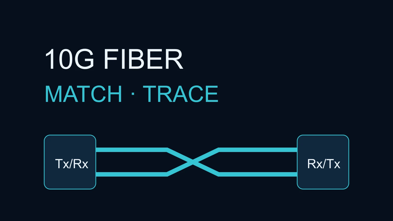
When a 10G uplink between business switches will not come up, check host support, the optical standard at both ends, the entire fiber path and Tx-to-Rx polarity before replacing equipment. Then inspect connector end faces and compare receive power, interface counters and logs. An LC connector that fits, or an optic that appears in inventory, does not prove compatibility. Change one variable at a time and verify stability and the intended business traffic before accepting the link.
Scope and prerequisites
This procedure covers point-to-point, dual-fiber, duplex-LC 10G Ethernet links between office floors, equipment rooms and aggregation switches. It focuses on 10GBASE-SR and 10GBASE-LR. SR and LR define different optical interfaces; the same connector does not make them interchangeable. Single-fiber BiDi, wavelength multiplexing, PON, 40G/100G and copper DAC are outside this procedure.
Collect both switch models, port identifiers, software releases, full optic part numbers, fiber categories and patch-panel routes. Arrange read access to device state, a maintenance window, supported known-good replacement optics, matching patch leads, and appropriate inspection and cleaning tools. Record the original connections and rollback path before touching a live uplink. Without an approved window, begin with read-only checks.
This is a procedure synthesized from vendor documentation, not a Yuqi customer case or a field test. The Cisco Catalyst 9000 commands below are official documentation examples and were not executed for this article. Other platforms require their own command references. For overall project handover, see the office network deployment and acceptance checklist; this article addresses its optical physical-link component.
Check both optics and the complete fiber path
Check the A-end patch lead, distribution panel, backbone, splices and B-end lead together. Replacing a patch lead with single-mode fiber does not convert a multimode backbone into a single-mode path.
| Check | SR path | LR path | If the check fails |
|---|---|---|---|
| Optical standard and speed | Matching 10GBASE-SR interfaces at 10G | Matching 10GBASE-LR interfaces at 10G | Verify both part numbers and host support; do not pair SR with LR |
| Fiber medium | Supported multimode fiber, MMF | Supported single-mode fiber, SMF | Check installation records and cable markings, not jacket color alone |
| Reference wavelength | 850 nm | 1310 nm | Confirm the actual part-number specification |
| Reach and loss | Fiber grade, connections and optic specification | Actual path and optic specification | Stop acceptance if the route is unknown or outside specification |
| Connector and polish | Duplex LC with approved polish | Duplex LC with approved polish | Do not force APC connections into a PC/UPC optical interface |
As a specific vendor example, Cisco lists a maximum of 300 m on OM3 and 400 m on OM4 for SFP-10G-SR, and 10 km on G.652 single-mode fiber for SFP-10G-LR. These are module specifications, not measured reach or throughput guarantees. The same table specifies a 2 m minimum cabling distance for SR/LR and certain other modules. Even a short bench test must respect the actual optic's minimum distance and receive-power ceiling. Consult the complete Cisco data sheet; do not apply one part number's limits to another.
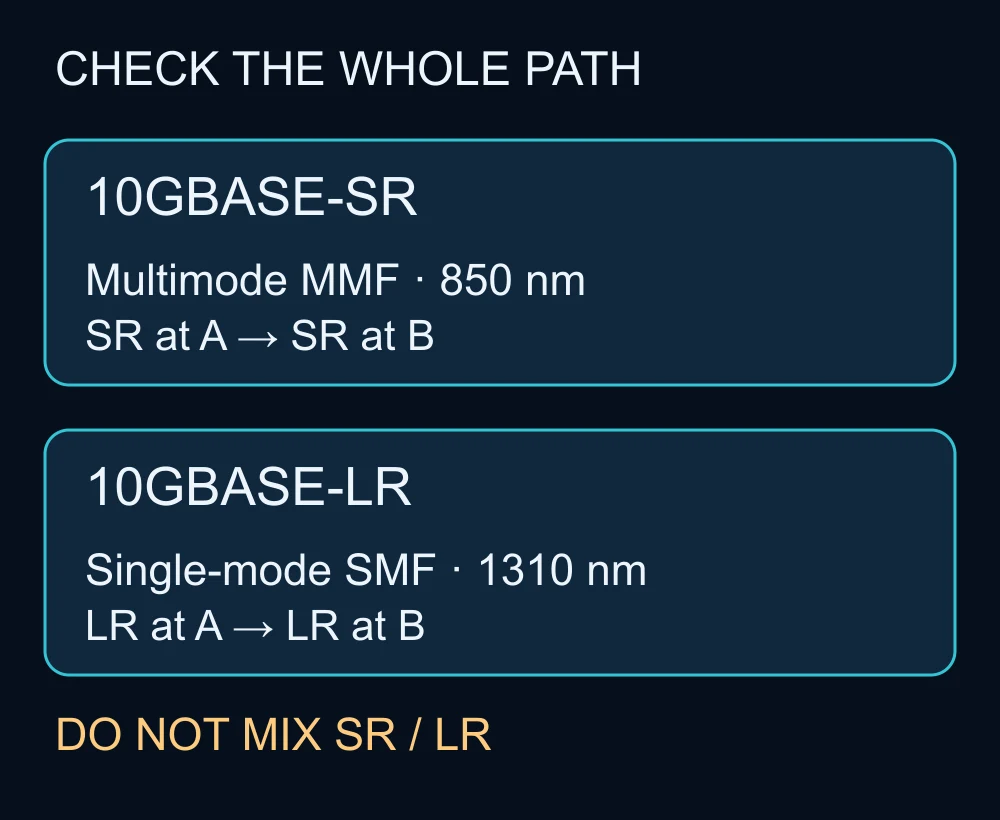
For mixed-vendor connections, verify each host's support for its local optic and the interoperability of the two optical interfaces. An MSA claim is not a substitute for the host, port and software support matrix. The scope of selection and installation can be discussed through Yuqi network equipment services. Bypassing unsupported-optic checks is not the default remedy.
Why duplex LC does not identify a 10G optic
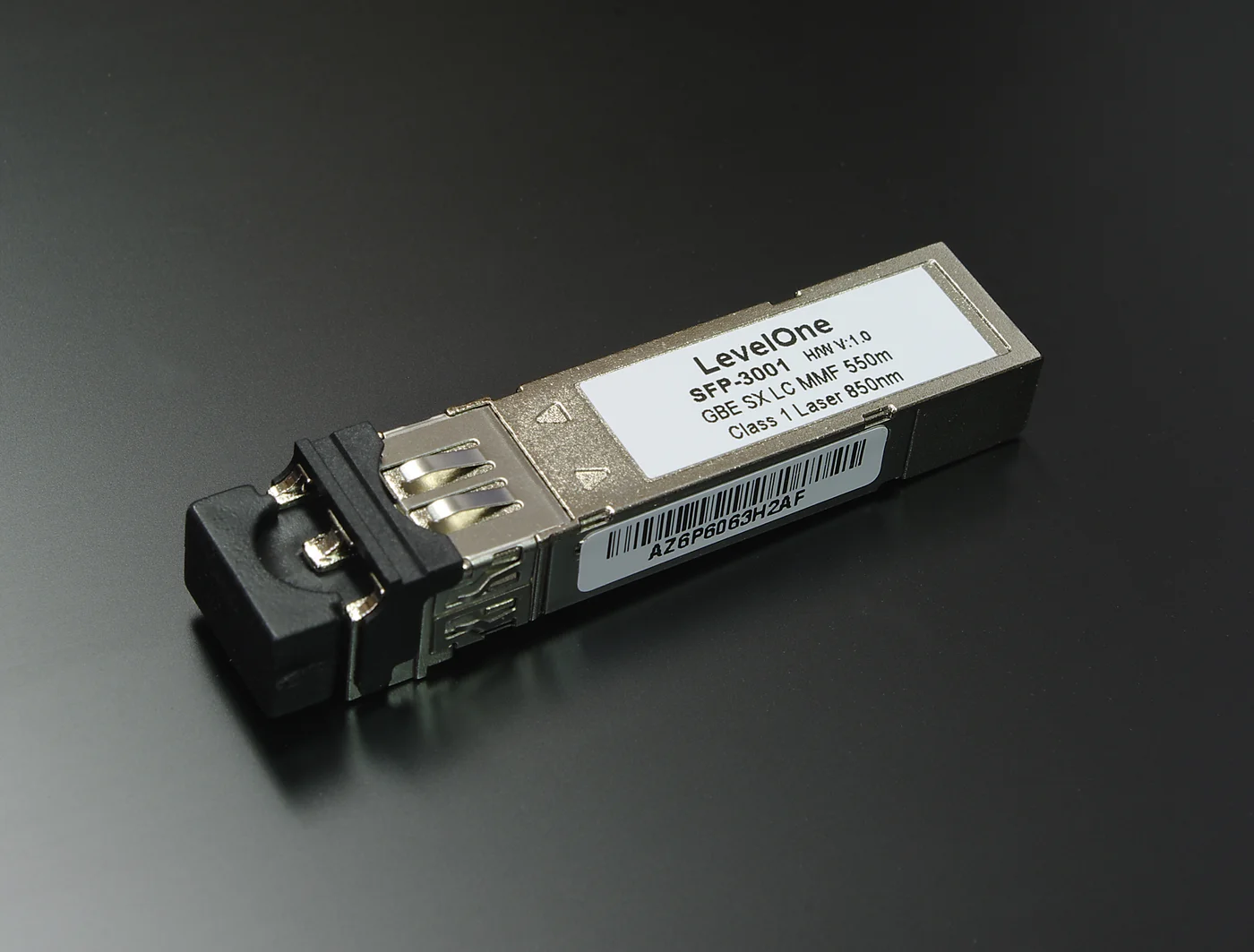
Photograph the labels of both actual modules and record their part numbers, speed, standard, serial numbers and installation positions. Compare labels with procurement records and device inventory. If a label cannot be read, or inventory disagrees with it, pause identification and acceptance. A latch color is only a clue.

Check polarity, end faces and receive power in order
- Preserve a baseline. Capture both ends' administrative and operational states, optic identification, counters and logs in the same time window. An administratively disabled port and a loss of optical signal require different decisions. Establish why a port is disabled before approving activation.
- Trace both strands. A Tx must reach B Rx, and B Tx must reach A Rx. Follow panel and patch-lead labels through the path. Change strand order at one end only on an identified test link during an approved window, documenting rollback first. Swapping both ends preserves the original wrong relationship.
- Inspect safely, clean if needed, and reinspect. Confirm the optical source is disabled and use a suitable inspection instrument and the manufacturer's procedure. Do not look into a port with your eyes or an unverified microscope. A new lead or dust cap does not establish cleanliness. Use the specified materials and avoid excessive bends. Follow the vendor inspection and cleaning procedure.
- Read DOM at both ends. Digital optical monitoring can report supported modules' temperature, voltage and transmit/receive power. Compare A Rx with B Tx and B Rx with A Tx; preserve units and timestamps. dBm is a logarithmic power unit, not a percentage. The same-direction Tx-minus-Rx difference is in dB and may help estimate loss, but does not replace a calibrated link test.
- Replace one variable at a time. In the maintenance window, try a matching known-good lead, optic or port and retain before/after evidence. Do not change both optics and the backbone simultaneously. Before moving a port, check the intended VLAN, aggregation and speed configuration.
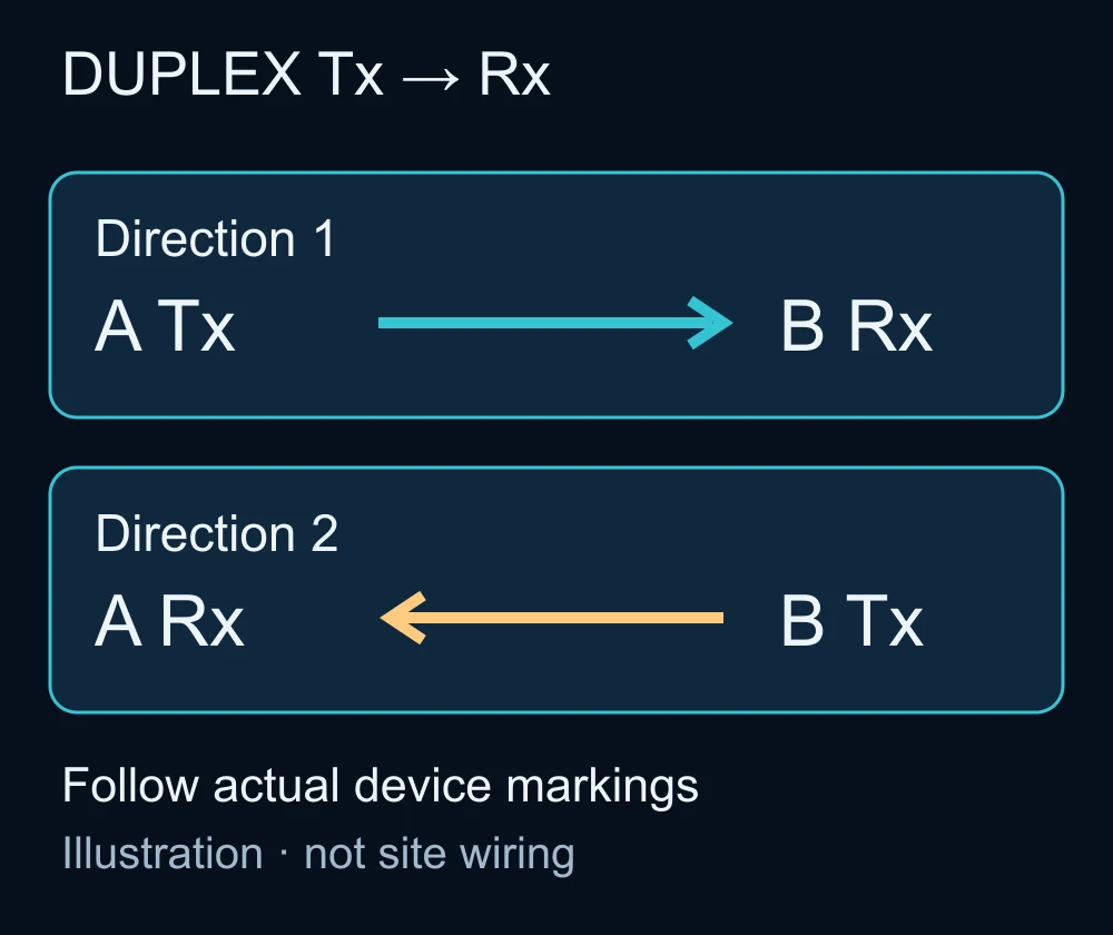
Cisco's installation notes address Tx/Rx identification and LC end-face inspection. Its Catalyst 9000 troubleshooting guide supports evidence collection from logs, counters and DOM. DOM is not available for every optic; copper TDR does not test fiber.
The following are read-only examples from that official guide. The port identifier is the guide's example, and these commands were not run for this article. Verify syntax, permissions and output fields for the actual platform and release.
Read logs on switches A and B. This returns transitions for multiple interfaces; identify the actual port and align timestamps. No matching lines can mean the log was not retained.
show logging | include changed
Read the affected interface. tenGigabitEthernet 1/0/40 is the official example port; replace it with the real local interface before copying. Use the remote switch's own port identifier at the other end.
show interfaces tenGigabitEthernet 1/0/40
Inspect administrative/operational state, 10Gb/s, media type, CRC and input errors. For administratively down, establish why it was disabled. For up/up with failed applications, check VLAN, aggregation and routing. Save a starting counter value and rerun after the agreed observation period; subtract start from end. A reset or counter clearing invalidates that interval and requires a new baseline.
Next read port DOM. This adapts the official show interfaces {interface} transceiver detail syntax to a 10G example port. It is an unverified platform adaptation, not a guarantee that every Catalyst release accepts it; consult the actual command reference first.
show interfaces tenGigabitEthernet 1/0/40 transceiver detail
Find Transmit Power, Receive Power, dBm units and ++ / + / - / -- alarm markers, then collect the same fields remotely. If the syntax is unsupported or DOM is not enabled, consult the platform guide or measure externally. Do not change global monitoring configuration merely to force a reading.
Copy this record template; it is neither a command nor a measured result. Enter UNKNOWN for missing evidence or N/A with a reason.
Timestamp and time zone:
Switch A / port / software release:
Switch B / port / software release:
A optic part number / standard / support reference:
B optic part number / standard / support reference:
End-to-end fiber category / length / panel route:
A Tx → B Rx and B Tx → A Rx verified:
A Tx / A Rx (dBm) / specified receive range:
B Tx / B Rx (dBm) / specified receive range:
DOM alarms / end-face inspection:
Observation start/end / load:
A and B CRC start / end / delta:
Single component replaced / before-and-after result:
Target application / expected / actual result:
Rollback connection / open issues / acceptance owner:
Expect interface transition timestamps, speed, error counters and supported optics' power values. Unsupported commands, N/A DOM fields, insufficient permissions or rotated logs mean missing evidence. Consult the platform reference or use a suitable optical power meter; do not substitute zero or declare a pass. This procedure does not require debug, counter clearing or shutdown/no shutdown.
Use symptoms to narrow the fault, not to prove it
| Symptom | Check first | Limit of the conclusion |
|---|---|---|
| Optic absent or unsupported | Part number, host/software support, seating | Does not prove a broken fiber; do not bypass checks by default |
| Both receive readings low or unavailable | Transmit state, polarity, route, breaks and end faces | Missing DOM is not zero optical power |
| Only one receive direction abnormal | Remote transmitter, that strand and its connections | Correlate both ends or obtain instrument evidence |
| Receive power above maximum | Module selection, power limits and short-link conditions | Do not add an attenuator without a specification-based design |
| Power in range but link down or flapping | Speed support, port settings, optic faults and error trend | Normal optical power does not establish protocol or business success |
| Link up, business traffic fails | VLAN, aggregation, routing, policy and endpoints | Move to logical-network checks instead of blindly replacing optics |
Evaluate receive power against the actual part number's operating range and the device's DOM alarms, checking both upper and lower limits. A universal rule such as “above −10 dBm is healthy” is inappropriate. If DOM thresholds disagree with the data sheet, verify module identity, calibration and platform support before deciding. Alarm thresholds alone are not a complete link-performance guarantee.
Apply the fix and verify its effect
- Confirmed SR/LR or media mismatch: preserve the baseline, then select matching optical standards and patch leads supported by both hosts for the verified backbone medium. If fiber grade or length is unknown, measure it first. After replacement, recheck both receive ranges, link state and error deltas.
- Confirmed wrong polarity: during the approved window, change strand order at one end only. Verify A Tx→B Rx and B Tx→A Rx, then reread both receive powers and states. If there is no improvement, restore the documented connection rather than repeatedly swapping strands.
- Confirmed contamination: disable the optical source, clean with the appropriate procedure and reinspect. After reconnecting, compare same-direction receive power and error deltas. Replace an unsuitable lead or damaged connector; “cleaned” does not mean inspection passed.
- Recovery after a single replacement: retain part numbers and before/after state plus stable-observation evidence, and isolate the suspected component under the maintenance procedure. An unexplained intermittent recovery leaves the root cause open and is not a completed handover.
An editorial calculation, not a field measurement: if A Tx is −3 dBm and B Rx is −6 dBm, their same-direction difference is 3 dB. This does not establish acceptance. Check B's receive range, calibration, connection points and actual traffic. Do not subtract measurements from different directions.
Define acceptance evidence and failure gates
Freeze the test plan before changing the link. Observation duration, traffic load, loss, throughput and error limits must come from the business requirement and contract; this article supplies no universal passing numbers. For a new link, no increase in relevant physical errors such as CRC/FCS during the observation period is a useful proposed target. Any different allowance needs an explicit basis.
| Acceptance area | Evidence to preserve | Fail or pause when |
|---|---|---|
| Selection and route | Both part numbers, support matrix, fiber grade, length, connections and port map | Support unresolved, SR/LR or media mixed, route outside specification |
| Optical state | Same-window bidirectional Tx/Rx, units, operating ranges, alarms and inspection record | Receive limits exceeded, anomalies unexplained or necessary measurements missing |
| Link stability | Both-end state, log window, counter deltas and duration | Unexpected flaps or continuing related errors |
| Business verification | Agreed endpoints, VLAN/aggregation, application/load and expected versus actual result | Only the LED or ping works; target applications or redundancy remain untested |
| Rollback and handover | Final wiring, spares, change record, rollback route and owner | Original connection cannot be restored or root cause remains unknown |
If throughput is in scope, use controlled traffic or an agreed test tool in an isolated or approved window. A port labeled 10G is not a measured throughput result. Redundancy testing requires its own approval and evidence. For a multi-device project, system integration services can help define physical-link, logical-network and business acceptance responsibilities.
FAQ
Can SR connect directly to LR?
Do not mix conventional dual-fiber 10GBASE-SR and 10GBASE-LR in this procedure. Check the optical standards, wavelengths and media at both ends; matching connectors are insufficient.
Why does changing an LC patch lead not fix the link?
LC describes a connector, not speed, the optical standard or the entire fiber route. New end leads cannot fix an incompatible backbone, wrong polarity or a break elsewhere.
Does missing DOM mean the optic must be replaced?
No. Check whether the part number and platform support DOM and obtain instrument measurements when needed. An absent reading alone does not establish a defective module.
Does a short LR link need an attenuator?
Use the actual module's minimum distance, transmit maximum and receive maximum. “LR” or “10 km” alone is not enough to justify attenuation. Resolve selection issues before applying a documented remedy.
What still needs testing after the link LED comes on?
Check both ends' error deltas, unexpected transitions, target applications and redundancy behavior. The LED covers only a limited part of acceptance.
Related solutions
Network equipment selection and configuration · System integration
Related reading
Office network deployment and acceptance checklist
For help defining the checks, share sanitized switch models, optic part numbers, a fiber-path diagram and the fault time window with Yuqi.