
Verify four things: power, notification, protective action and recovery. Connect the NAS to a battery-backed outlet, make sure DSM receives the power event, allow enough battery time to complete protection, then check storage, files and applications after power returns. A lit NAS, a UPS alarm or an unreachable web interface is insufficient acceptance evidence.
This guide treats a Synology NAS and USB UPS as a small business deployment project for departmental files and backup storage. Settings follow vendor documentation; the timing calculation and PowerShell snippets are operating examples. No customer-site power outage test was performed for this article.
Define the project scope, responsibilities and deliverables
The objective is to protect the NAS during a mains outage and restore shares and applications in an agreed way afterward. Continuous operation throughout an extended outage is outside this objective. Start with one NAS whose storage and file services already work. For a new NAS, disk initialization, access permissions and data migration need their own acceptance checks first.
| Project stage | Implementation work | Deliverable |
|---|---|---|
| Site survey | Identify power sources, NAS, communication ports, network dependencies and downtime needs | Equipment/load inventory, original settings, recovery objective |
| Design and delivery inspection | Check exact models, W/VA ratings, data cable and outlet groups | Wiring plan, timing budget, manuals and compatibility evidence |
| Installation | Shut down cleanly before moving power, connect USB and save DSM policy | Cable labels, device information and configuration captures |
| Controlled testing | Verify short interruptions first, then protection and recovery | Two event timelines, logs and exception records |
| Acceptance and handover | Check files/apps, restore scheduled tasks and assign owners | Acceptance sheet, final settings, rollback and retest conditions |
The IT administrator owns NAS settings and evidence. The business owner confirms write suspension, recovery order and application results. An onsite operator controls the approved mains interruption and restores input power. One person may fill several roles, but the test needs someone onsite who knows the abort point and recovery method.
Survey the environment and agree on downtime
The baseline is a genuine Synology NAS running DSM 7 and a USB UPS with a supported communication interface connected directly to the NAS. Capture the actual interface because labels and behavior can vary by DSM build and UPS model. High-availability clusters, dual-controller systems, SNMP deployments and custom NUT servers need separate designs.
Record the NAS model, full DSM build, exact regional UPS model, firmware, battery replacement date, outlet groups, protected loads and original settings. Check the exact combination in the Synology UPS compatibility list, including who tested it. Synology warns that firmware or hardware changes can affect compatibility and that USB hubs are unsupported. A brand match is insufficient.
Arrange a window in which file shares and applications may stop. Before testing, the business owner sets a recovery deadline from stable mains restoration to completed checks of specified shares and applications. Record the value, start/end events and application list. Exceeding it fails the recovery objective; NAS startup alone is insufficient. Confirm a usable backup, keep evidence outside the protected NAS and assign an onsite recovery owner. Do not simulate an outage during storage repair, rebuild, expansion or a firmware upgrade. If your backup recovery exercise cannot recover the required data, address that gap first.
| Precondition | Evidence to retain | Hold point |
|---|---|---|
| Healthy storage | Pool, volume and drive status | Degraded/crashed storage or critical maintenance |
| Suitable battery and load | Charge state, alarms, total W/VA, vendor runtime information | Battery alarm, overload or inadequate timing margin |
| Workloads can pause | User notification, write suspension, application recovery order | Unmanaged writers, databases or virtual machines |
| Test can be reversed | Input location, recovery operator, original settings | No onsite operator or ambiguous input/output cables |
Prepare the equipment and installation plan
Complete an inventory before procurement. A brand name or a single VA rating does not define the solution. Apply the same checks to existing equipment and mark missing readings as unknown.
| Required item | Verify | Insufficient substitute |
|---|---|---|
| NAS and power adapter | Full model, DSM, workloads, electrical input and plug | “Four-bay NAS” |
| UPS | Regional model suffix, W/VA, outlets, communication and vendor runtime data | A photograph of a similar product |
| Data cable | Vendor-approved cable, port type and usable length | Charge-only cable or USB hub |
| Power accessories and network devices | Suitable cables, outlet count, dependencies and actual load | Unplanned power-strip chains or omitted switch load |
| Evidence and recovery tools | Management computer, separate record location, fixed test file and clock | Evidence stored only on the protected NAS |
Before moving the NAS power connection, stop writes and shut it down normally through DSM. Once it has stopped, move its power input to a verified battery-backed UPS outlet. Confirm the UPS, battery and connections according to their manuals, start the NAS and recheck baseline shares and applications. Do not move a running NAS by unplugging its power input.
Wire power and status as separate paths
The UPS supplies electrical power; USB carries status to DSM. Check both independently. A USB charging port is not necessarily a UPS communication port, and an RJ45 surge-protection socket is not necessarily a management interface. Use the actual model manual to identify ports and cables.
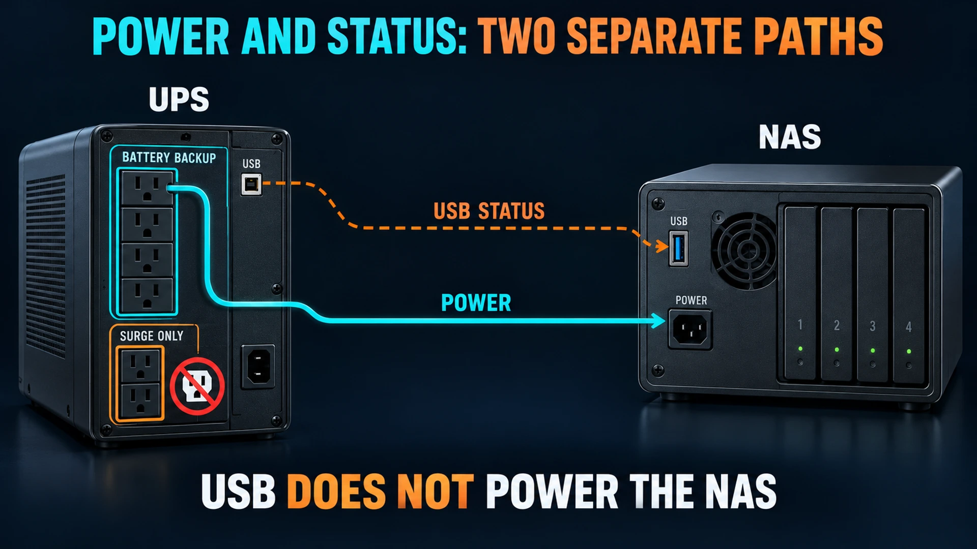
Trace the NAS adapter to an outlet explicitly marked for battery backup. Some UPS units also provide surge-only outlets without battery support. APC's UPS buying guide distinguishes these outputs and requires checking both watt and VA limits. A VA figure is not a runtime in minutes.
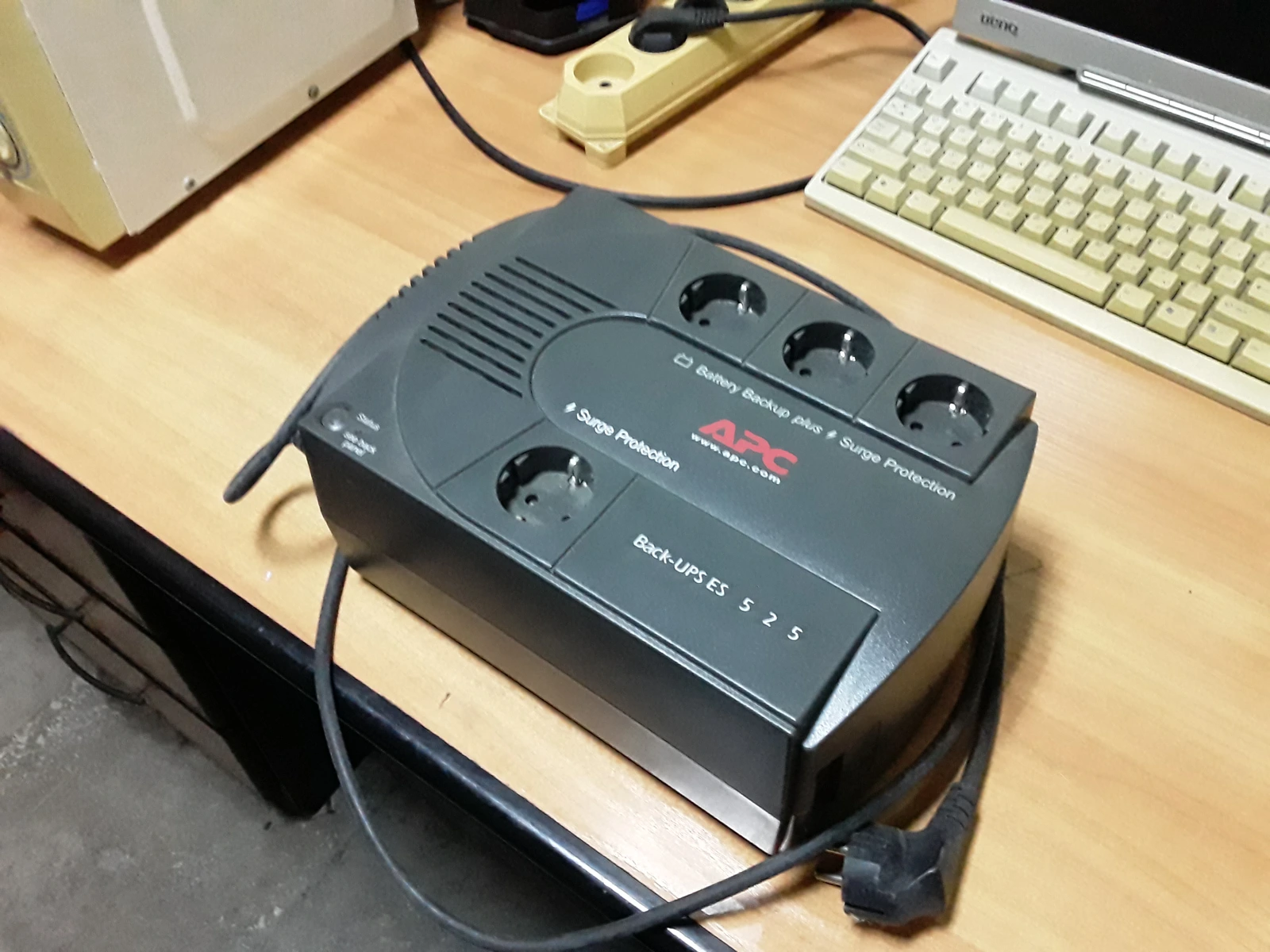

A single NAS with direct USB does not require a switch to receive UPS status. Remote observation still needs the management computer and network to stay available. Losing network access cannot establish whether storage protection completed.
Configure DSM and budget time for protection
Open Control Panel → Hardware & Power → UPS, enable UPS support, select USB UPS and inspect Device Information. Verify the detected device and available status, then apply the settings. Missing information or the wrong device means investigating the cable, direct port and compatibility before interrupting mains power.
Choose low-battery triggering or a custom delay before Standby Mode. DSM stops services and unmounts volumes in standby protection; low battery can trigger it before the chosen delay expires. Standby does not establish that UPS output is off. Use the DSM 7 UPS help for the supported settings and behavior.
Do not copy a universal five-minute delay. Budget the permitted interruption wait, time to finish protection and a margin for battery aging and variable conditions. This calculation is a planning example, not measured runtime:
Usable battery runtime > Wait + Protection completion time + Margin
Example: 120 seconds + 90 seconds + 180 seconds = 390 seconds (6.5 minutes)
390 seconds is a budget requirement, not a UPS runtime guarantee.
Measure completion time on the actual configuration. A displayed runtime estimate does not replace controlled testing. Include actual switch/router loads in the total. Reassess if load or completion time increases or a battery alarm appears. If margin cannot be established, shorten the delay or change the equipment/load design; do not exhaust the battery to demonstrate maximum runtime.
“Shut down UPS when the system enters Standby Mode” is a separate capability. The linked Synology help explicitly states that enabling it makes the NAS shut down immediately upon loss of the power source. Do not assume the custom delay will still apply or infer a harmless delayed notification from the option name. UPS shutdown support varies by model and affects other powered loads.
Record the original value before the first short-interruption test. If enabled, the administrator temporarily clears it and applies the change during the agreed maintenance window. If policy cannot be changed, skip that short test and design a separate test allowing immediate NAS exit. Restore the original value after initial communication checks. Test the final policy with this option only after verifying model instructions, every affected load's exit sequence and recovery method. A test with it temporarily disabled does not validate the final policy.
For unattended recovery, check the restart-after-power-failure setting under General → Power Recovery. The DSM 7.2 user guide identifies this control; use the wording in your installed build. NAS restart and UPS output restoration are separate behaviors to validate together.
Commission in two rounds: notification, then protection
Pause scheduled backup/sync tasks and ask clients to stop writes. Databases and virtual machines need their application-specific exit or relocation procedures. Avoid active production files as a power-loss test target. Prepare a fixed-content file in a dedicated test share, finish its upload and capture the baseline.
Round one: a short mains interruption
The onsite operator interrupts only the UPS mains input using the manufacturer-approved method. Keep NAS output power, USB and required networking connected. Prefer an approved input switch that maintains protective earth. Do not pull NAS power, open the UPS or operate an unidentified electrical circuit.
After confirming that the UPS-shutdown option is disabled as described above, restore mains before reaching the standby threshold. Look for battery operation without immediate NAS power loss and a corresponding DSM event or configured notification. Record timestamps, UPS status and the NAS event, then verify restored mains status. This round establishes short-duration power and notification, not completed workload exit. If low battery triggers protection early, immediately restore input and follow the protection recovery procedure.
If the NAS loses power immediately, restore input and investigate outlet grouping, battery, overload and the adapter path. If the UPS is on battery but DSM has no event, investigate communication rather than waiting longer. A failed first round blocks the second round.
Round two: reach the protection condition
Recheck charge and load, then apply and capture the final target policy. With UPS shutdown disabled, verify the configured wait or low-battery trigger; with it enabled, prepare and retain evidence for the immediate-exit behavior stated by Synology rather than waiting for the original custom delay. Set an abort time earlier than the battery budget's exhaustion and assign the person who will restore input. Record protective events and device state. A failed ping, stopped fan or dark LED cannot independently prove that volumes were unmounted. If available records cannot confirm protection, record insufficient evidence and stop extending the test.
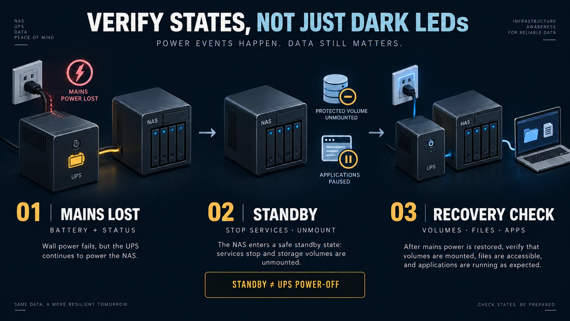
If protection misses the budget, an unexpected battery alarm appears, output becomes abnormal or communication is lost, immediately restore UPS mains input and follow the recovery plan. Do not wait for battery exhaustion or force NAS output off. Preserve the failed test record before diagnosis.
After mains returns, separately record UPS output restoration, NAS startup or service recovery and share availability. Check Storage Manager and logs: pools/volumes are healthy, with no new abnormal-shutdown or relevant storage events. Restore workloads in their agreed order. If the NAS stays in standby or does not start, recover it under the model instructions and onsite plan. Manual intervention fails an unattended-recovery objective; repeated hard power cuts do not establish automation.
Check files, applications and acceptance evidence
On a Windows management computer, use Windows PowerShell 5.1 or PowerShell 7 to compare SHA-256 for the same dedicated test file. Replace the NAS address, share, file and record path below. Read permission is required, the file must exist and its content must remain fixed. These are operating examples. The local record directory must exist and be writable; stop acceptance if saving fails. Use a distinct record name for each run and retain earlier baselines. Keep the baseline on the management computer. The second block works in a new session.
Before testing:
$TestFile = '\\nas.example.com\ups-test\probe.bin'
$RecordPath = Join-Path $env:USERPROFILE 'Documents\ups-probe-baseline.clixml'
Get-FileHash -LiteralPath $TestFile -Algorithm SHA256 -ErrorAction Stop |
    Export-Clixml -LiteralPath $RecordPath -NoClobber -ErrorAction Stop
After recovery:
$RecordPath = Join-Path $env:USERPROFILE 'Documents\ups-probe-baseline.clixml'
$Before = Import-Clixml -LiteralPath $RecordPath -ErrorAction Stop
$After = Get-FileHash -LiteralPath $Before.Path -Algorithm SHA256 -ErrorAction Stop
if ($After.Hash -ne $Before.Hash) {
    throw 'UPS test file hash mismatch'
}
$After | Select-Object Path, Algorithm, Hash
The parameters follow Microsoft's Get-FileHash reference. A matching hash establishes the selected file's content only. It does not prove all files, database transactions or volumes survived intact. A command error requires distinguishing path, permission, network and file-change issues before diagnosing a drive fault. Applications, databases and virtual machines need separate startup, read/write and consistency checks.
| Acceptance item | Evidence required | Failure or insufficient evidence |
|---|---|---|
| Power | NAS stays powered from battery-backed output after input loss | Immediate loss, overload or wrong outlet |
| Communication | UPS battery status corresponds to a NAS event | UPS on battery with no NAS notification |
| Protection | Protective event/state records within the timing budget | Only an unreachable NAS or an unconfirmed state at abort time |
| UPS shutdown, if enabled | Actual model follows the sequence after all affected loads exit | Unsupported function or premature interruption of another load |
| Recovery | Observed process meets the manual/automatic objective | Manual recovery described as unattended |
| Data and workloads | Separate storage/log, file-hash and application records | New alarms, content differences or unrecovered workloads |
Restore notifications and scheduled tasks paused only for testing, and return temporary option changes to their original values. Retain the accepted target values for permanent deployment settings, compare them with final captures and apply them; recheck device information and business services. Restore permanent changes to pre-change values only when rolling back a failed deployment. Retest after model/battery changes, DSM/UPS firmware updates or added loads.
Roll back power and configuration in that order
First restore UPS mains input and confirm stable power. Recover the NAS according to its state and model instructions. Preserve events and configuration differences. If a failed UPS must be bypassed, schedule a normal NAS shutdown before moving its power connection; never remove running output power as a rollback shortcut.
| Symptom | Inspect first | Repair and retest |
|---|---|---|
| NAS immediately loses power | Backup outlet group, battery, overload, adapter path | Fix power and repeat round one; check new storage alarms |
| UPS on battery, no DSM event | Data cable, direct port, actual compatibility | Restore input, repair communication, verify Device Information and round one |
| Protection incomplete at abort time | Policy, observed duration, load and margin | Restore input immediately; revise budget and reschedule |
| No recovery after mains returns | UPS output, DSM recovery setting, actual state | Recover under the plan; fail and retest an automatic objective |
| Hash difference or application error | File changes, permissions, application and storage logs | Preserve differences and use the backup/application recovery procedure |
Restore original values from the pre-change captures, then verify power, device recognition and business baseline. A successful rollback restores the previous environment; it does not pass the failed deployment.
Extend to a second NAS only with a protected notification path
With one NAS reading USB status and a second using Synology UPS server, notification crosses the network. Enable the server, permit only required NAS addresses and configure the correct server address on the client. The connecting switch needs battery-backed power from the same UPS; otherwise notification may disappear first. The DSM UPS help states the network requirements.
Allow clients enough time to finish protection before the server exits. Retain events and recovery evidence from both devices; one successful NAS does not validate the other. High-availability deployments use the separate Synology SHA UPS guide, not this single-NAS acceptance record. Use Data Center Infrastructure to include network dependencies when scoping the project.
Hand over records the operations team can use
Provide an asset-labelled wiring plan, equipment/load inventory, final DSM/UPS settings, both test timelines, logs, hash records, application results, exception/rollback records and retest conditions. Enter actual values and evidence locations. Leave unmeasured items blank with reasons.
Assign battery maintenance, alert ownership and application recovery order. Record the manufacturer's maintenance guidance. Reassess timing before adding loads, and retest after battery, firmware or topology changes. Communication loss or a battery alarm requires repair and revalidation rather than silencing the notification.
Frequently asked questions
Does a displayed UPS model mean protection is ready?
It is one communication check. Actual output power, event changes, protective action and recovery still need evidence.
Does Standby Mode mean both NAS and UPS are off?
No. Record standby protection, final NAS shutdown and UPS output shutdown separately, including effects on other powered devices.
Can a successful UPS self-test replace commissioning?
It does not establish NAS notification, workload-exit order or business recovery. Treat the model's self-test as one precondition.
Can a UPS replace backups?
No. It supports temporary power and orderly exit. File versions, independent copies and recovery exercises address deletion, ransomware and application damage.
Related solutions
Use YUQI's Business Continuity Planning to review protected loads, network dependencies and application recovery order together.
Related reading
If your NAS still reports abnormal shutdowns, bring the exact models, wiring and event timeline to YUQI to define a practical protection scope and commissioning window before changing equipment.